
High-speed hydraulic valve driving device and high-speed hydraulic valve

A driving device and hydraulic valve technology, applied in the field of high-speed hydraulic valves, can solve the problems that the digital hydraulic system does not show work efficiency, the rated flow performance lacks in-depth research, and the valve control energy consumption of the digital hydraulic system is small. The effect of step-by-step control of driving force, good hydraulic system adaptability, and fast dynamic coupling response

Pending Publication Date: 2019-03-26
CHINA AGRI UNIV
View PDF0 Cites 3 Cited by
  • Summary
  • Abstract
  • Description
  • Claims
  • Application Information

AI Technical Summary

Problems solved by technology

In particular, when the response time of the high-speed valve exceeds 1.5ms and the rated flow rate is less than 25L / min, the digital hydraulic system does not show superior working efficiency; while when the response time of the high-speed valve does not exceed 4ms and the rated flow rate exceeds 90L / min After that, the valve control energy consumption of the digital hydraulic system will tend to be minimized
In addition, in order to make up for the driving stroke of only tens of microns of the piezoelectric driver, the design of the main spool of the valve adopts the commonly used method in the field of compressors. The concept of perforated plate is used to obtain a larger flow area, but its rated flow is still only 28L / min, and the cost of piezoelectric actuators is higher than that of traditional solenoid electromagnetic actuators
The current high-speed hydraulic design focuses more on improving the response speed of the valve, but there is a lack of in-depth research on other aspects of performance such as improving the valve's rated flow rate and structural ease of insertion.
In addition, the current research on high-speed valves focuses on high-speed on-off valves, and the lack of research on high-speed proportional valves makes these new high-speed valves only suitable for a specific digital hydraulic system, resulting in very limited applications.

Method used


Image

  • High-speed hydraulic valve driving device and high-speed hydraulic valve
  • High-speed hydraulic valve driving device and high-speed hydraulic valve
  • High-speed hydraulic valve driving device and high-speed hydraulic valve

Examples


Embodiment

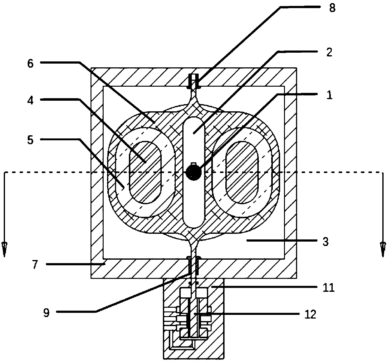
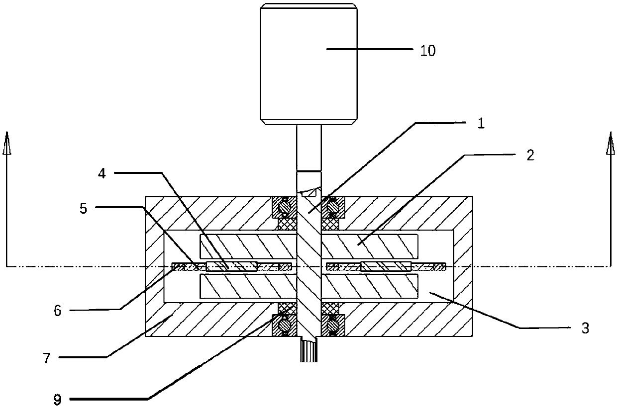
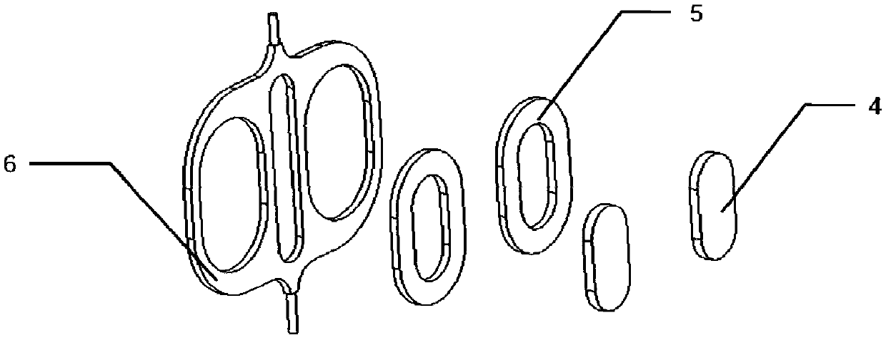
[0032] A structural schematic diagram of a driving device for a high-speed hydraulic valve and a high-speed hydraulic valve described in this embodiment is shown in Figure 1 to Figure 3 shown.

[0033] This embodiment takes the structure equipped with two turntables as an example to illustrate the driving device of the high-speed hydraulic valve and the structure of the high-speed hydraulic valve, but those skilled in the art can understand that the driving device of the high-speed hydraulic valve equipped with one or more turntables The structure principle is the same.

[0034] Such as Figure 1-3 As shown, a driving device for a high-speed hydraulic valve described in this embodiment consists of a rotating shaft 1, two turntables 2, a magneto-rheological fluid 3, two magnetic cores 4, two excitation coils 5, a The linear translator 6, a housing 7, two bearings 8, three sealing rings 9 and a hydraulic pump 10 are composed. The rotating disk 2 is made of a magnetically con...


PUM


Abstract

The invention discloses a high-speed hydraulic valve driving device and a high-speed hydraulic valve. The high-speed hydraulic valve driving device is composed of a rotating shaft 1, a rotating disc 2, two magnetic conductive iron cores 4, two magnet exciting coils 5, a linear translational motion part 6, a shell body 7, a bearing 8, a seal ring 9 and a driving motor 10, wherein the rotating disc2 is fixedly connected on the rotating shaft 1, the linear translational motion part 6 is installed beside the rotating disc 2, the two sides of the linear translational motion part 6 are provided with symmetrical installation holes, the two magnet exciting coils 5 are installed inside the installation holes in the two sides of the linear translational motion part 6 correspondingly, the two magnetic conductive iron cores 4 are installed inside the two magnet exciting coils 5 correspondingly, the shell body 7 is filled with magnetorheological fluid 3, and the driving motor 10 is connected withthe rotating shaft 1. The high-speed hydraulic valve driving device is fast in response speed, large in rated stroke, low in power consumption, capable of performing double-direction active driving onthe high-speed hydraulic valve, not affected by the system flowing direction, compact in structure, easy to be subjected to plug-in installation and capable of realizing switch control, reversing control and proportional control and has good hydraulic system adaptability.

Description

technical field [0001] The invention belongs to the technical field of high-speed hydraulic valves in hydraulic technology, and in particular relates to a driving device for a high-speed hydraulic valve and a high-speed hydraulic valve. Background technique [0002] Today's emerging high-efficiency and energy-saving hydraulic technologies all have a prerequisite for their application, that is, the maturity of high-speed hydraulic valve technology. Shortening the response time of high-speed hydraulic valves and increasing the rated flow rate (generally recorded as the rated flow rate when the valve port pressure drop is 5 bar) will improve the working efficiency of these emerging digital hydraulic systems. In particular, when the response time of the high-speed valve exceeds 1.5ms and the rated flow rate is less than 25L / min, the digital hydraulic system does not show superior working efficiency; while when the response time of the high-speed valve does not exceed 4ms and the...

Claims


Application Information

Patent Timeline
Patent Type & Authority Applications(China)
IPC IPC(8): F15B13/02F16K31/06
CPCF15B13/021F16K31/06
Inventor 熊绍平冯翔宇贾万波
Owner CHINA AGRI UNIV
Learn More