Macromolecule pipe wall pulse heating pipe

A pulsating heat pipe and polymer pipe technology, applied in indirect heat exchangers, lighting and heating equipment, etc., can solve problems such as restricting the large-scale use of pulsating heat pipes, reduce the risk of surface scaling, increase preload, improve The effect of heat exchange efficiency

Pending Publication Date: 2019-03-26
苏州图卡节能科技有限公司
View PDF0 Cites 2 Cited by
  • Summary
  • Abstract
  • Description
  • Claims
  • Application Information

AI Technical Summary

Problems solved by technology

[0003] Traditional heat pipes generally use metal as the tube wall material. In order to facilitate the observation of the fluidity of the heat pipe, glass or other non-metallic transparent materials are also used as the material of the heat pipe. Among them, the pipes that transport the cold and heat sources are mostly circular or oblate pipes. In order to reduce thermal resistance, most of them use uniform temperature copper plates or metal plates as the heat conduction medium to connect the pulsating heat pipes, or directly immerse the pulsating heat pipes in the heat source or In the cold source, the large-scale use of pulsating heat pipes is greatly limited

Method used


Image

  • Macromolecule pipe wall pulse heating pipe
  • Macromolecule pipe wall pulse heating pipe

Examples


Embodiment

[0021] Example

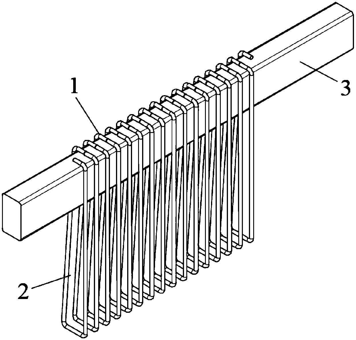
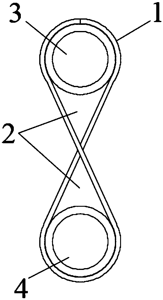
[0022] like figure 1 As shown, this embodiment provides a polymer tube wall pulsating heat pipe, which is a polytetrafluoroethylene tube body 1 with both ends closed. The tube body is a round tube with an inner diameter of 0.8mm and a wall thickness of 0.2mm. Medium fluorinated liquid Novec7100, the filling volume is 50% of the liquid volume capacity, the remaining space is Novec7100 saturated gas, the tube body is spirally wound into a rectangular cavity with a circular arc inside, and the tube body is partially wound on the outer periphery of the heat source for 16 turns , in close contact with the outer surface portion of the heat source 3 .

[0023] In the polymer tube wall pulsating heat pipe of this embodiment, as the temperature of the heat source rises, the heat of the heat source is transferred to the inside of the heat pipe to heat the internal working medium Novec7100, and the power generated by the violent gasification phase transition drives the ...


PUM


Abstract

The invention relates to a macromolecule pipe wall pulse heating pipe which comprises a heat pipe body. The heat pipe body is in a multi-circle spiral structure formed by winding a pipe made of a macromolecule material, a cavity is formed in the inner side of the single circle of the heat pipe body, one section, making contact with a heat source, of the heat pipe body is a heating section, one section, making contact with a cold source, of the heat pipe body is a cooling section, and at least one of the heat source and the cold source is arranged in the cavity in a penetrating manner, and makes contact with the inner wall of the corresponding heating section and the inner wall of the cooling section. According to the macromolecule pipe wall pulse heating pipe, the multi-circle spiral structure formed by winding the pipe made of the macromolecule material is adopted, the cavity is formed, the outside face of the cold source or the heat source is wrapped beneficially, pretightening forcecan be increased, contact heat resistance is reduced, the heat exchange efficiency is improved, and the heat loss is reduced. The problems that a traditional metal heating pipe is large in rigidity and cannot be closely attached to the non-planar interface of the heat source or the cold source easily are solved, corrosion resistance is possessed, and the risk of surface scaling is reduced. The pipe has high dielectric constant, the insulating effect is good, the pipe can be used for cooling the surface of an electrified part, the pipe forming efficiency is high, and the cost is low.

Description

technical field [0001] The invention relates to the field of pulsating heat pipes, in particular to a pulsating heat pipe with a polymer tube wall. Background technique [0002] In transportation, aerospace and industrial production processes, it is often necessary to heat or cool equipment systems or working media. Pulsating heat pipes, also known as oscillating heat pipes or self-excited oscillating heat pipes, were first proposed by scholar Akachi in 1990 and have a history of more than 20 years. Its potential high heat transfer effect and low production cost have become the focus of current research. . [0003] Traditional heat pipes generally use metal materials as the tube wall material. In order to facilitate the observation of the fluidity of the heat pipe, glass or other non-metallic transparent materials are also used as the material of the heat pipe. Among them, the pipes that transport the cold and heat sources are mostly circular or oblate pipes. In order to r...

Claims


Application Information

Patent Timeline
Patent Type & Authority Applications(China)
IPC IPC(8): F28D15/02
CPCF28D15/02
Inventor 蔡旺魏辉
Owner 苏州图卡节能科技有限公司
Why Eureka
Try Eureka