Photoelectric integrated rotation transmission system of high speed RapidIo signal and implementation method of rotation transmission

An implementation method and technology of a transmission system, which are applied in the field of high-speed RapidIo signal transmission, can solve problems such as the inability to realize high-speed RapidIo signal rotation transmission, and achieve the effects of stable and reliable implementation method, strong environmental adaptability, and high real-time performance.

Inactive Publication Date: 2019-03-26
JIUJIANG JINGDA MEASUREMENT TECH
View PDF0 Cites 3 Cited by
  • Summary
  • Abstract
  • Description
  • Claims
  • Application Information

AI Technical Summary

Problems solved by technology

Since the maximum rate of transmission signals of ordinary electrical rotary connectors can only reach hundreds of megabits, it is impossible to meet the rotary transmission requirements of high-speed RapidIo signals

Method used


Image

  • Photoelectric integrated rotation transmission system of high speed RapidIo signal and implementation method of rotation transmission
  • Photoelectric integrated rotation transmission system of high speed RapidIo signal and implementation method of rotation transmission
  • Photoelectric integrated rotation transmission system of high speed RapidIo signal and implementation method of rotation transmission

Examples


Embodiment 1

[0035] Example 1: Single-mode conversion

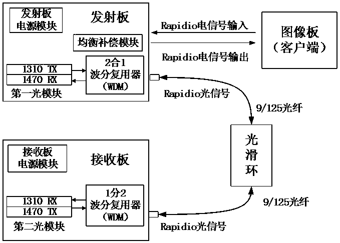
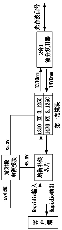
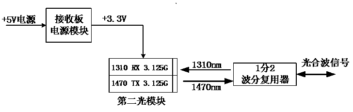
[0036] Such as figure 1 As shown, a high-speed RapidIo signal photoelectric integrated rotary transmission system is composed of a smooth ring, a transmitting board, and a receiving board, wherein: the smooth ring is a single-mode optical fiber rotary connector, which can realize the optical signal between the rotating part and the stationary part. uninterrupted rotation transmission; the launch board is composed of the launch board power module, equalization compensation module, the first optical module and 2 in 1 wavelength division multiplexer; the receiving board is composed of the receiving board power module, the second optical module and 1 minute 2 wavelength Demultiplexer composition;

[0037] The first signal terminal of the balance compensation module is connected to the signal input terminal of the client image board, the second signal terminal of the balance compensation module is connected to the first signal terminal of...

Embodiment 2

[0049] Embodiment 2: Multimode conversion

[0050] The structure of embodiment 2 is basically the same as that of embodiment 1, the difference is:

[0051] Such as Figure 4 As shown, there is also a third optical module with 850nm transceiver and 3.125Gbps on the receiving board. The first signal end of the third optical module is connected to the second signal end of the second optical module. The third optical module can realize 1310nm-850nm- 1470mn band multi-mode conversion.

[0052] The function of the receiving board can also realize multi-mode conversion in the 1310nm-850nm-1470mn band by using a third optical module integrating 850nm transceiver and 3.125Gbps. The specific implementation method is: the RapidIo electrical signal obtained by converting the second optical module of the receiving board The RapidIo optical signal converted into 850nm wavelength is looped through the multimode optical fiber line, and then the RapidIo optical signal of 850nm wavelength is ...


PUM


Abstract

The invention relates to a photoelectric integrated rotation transmission system of a high speed RapidIo signal and an implementation method of rotation transmission. The system is composed of a smooth ring, a transmitting plate and a receiving plate. The smooth ring is a single mode fiber rotation connector. The transmitting plate is composed of a transmitting plate power supply module, an equalization compensation module, a first optical module and a 2-in-1 wavelength division multiplexer. The receiving plate comprises a receiving plate power supply module, a second optical module and a 1-to-2 wavelength division multiplexer. When the system works, the transmitting plate carries out electrical-to-optical conversion on a RapidIo electrical signal input by a client to send a RapidIo optical signal, and the RapidIo optical signal is transmitted to the receiving plate through the smooth ring. The receiving plate receives the RapidIo optical signal and completes optical-to-electrical conversion and electrical-to-optical conversion to send the RapidIo optical signal, and the RapidIo optical signal is transmitted back to the transmitting plate through the smooth ring. The transmitting plate receives the RapidIo optical signal and completes optical-to-electrical conversion to output the RapidIo electrical signal to the client. Rotation transmission and full duplex communication of the high speed RapidIo signal are completed. According to the invention, the requirement of rotation transmission of the high speed RapidIo signal of a photoelectric detecting device in the monitoring field is met.

Description

technical field [0001] The invention relates to the transmission of high-speed RapidIo signals, in particular to a high-speed RapidIo signal integrated photoelectric rotary transmission system and a method for realizing rotary transmission. Background technique [0002] The photoelectric integrated rotary transmission system is composed of an electric rotary connector (ie, a conductive slip ring), an optical fiber rotary connector (ie, a smooth ring), and a photoelectric conversion circuit board. Among them, the electrical rotary connector and the optical fiber rotary connector are used to realize the rotary transmission of various electrical signals and optical signals. The photoelectric conversion circuit board includes a transmitting board and a receiving board, which play the role of electrical-optical-electrical conversion. Because optical transmission has the advantages of wide frequency band, large transmission data capacity, long transmission distance, and anti-elec...

Claims


Application Information

Patent Timeline
Patent Type & Authority Applications(China)
IPC IPC(8): G02B6/42
CPCG02B6/4215
Inventor 周萍于兵许建铮方志宇薄夫森
Owner JIUJIANG JINGDA MEASUREMENT TECH
Why Eureka
Try Eureka