Supercharge Your Innovation With Domain-Expert AI Agents!

A Time-to-Digital Converter Based on Delay Locked Loop

A delay-locked loop and time-to-digital technology, which is used in time-to-digital converters, electrical unknown time interval measurement, and time interval measurement devices, etc., can solve high power consumption, poor accuracy, and can not meet the practical application of vehicle lidar problem, to achieve the effect of reducing power consumption area, improving accuracy and stability, and improving anti-interference ability

Active Publication Date: 2020-06-19
XIDIAN UNIV
View PDF4 Cites 0 Cited by
  • Summary
  • Abstract
  • Description
  • Claims
  • Application Information

AI Technical Summary

Problems solved by technology

[0004] Current pulse wave lidar has been detected by the original single channel (see figure 1 ), developed into multi-line array scanning detection, and even large area array detection, which makes the time-to-digital conversion circuit also need to be area-array. High power consumption is far from satisfying the practical application of vehicle lidar

Method used


Image

  • A Time-to-Digital Converter Based on Delay Locked Loop
  • A Time-to-Digital Converter Based on Delay Locked Loop
  • A Time-to-Digital Converter Based on Delay Locked Loop

Examples


Embodiment 1

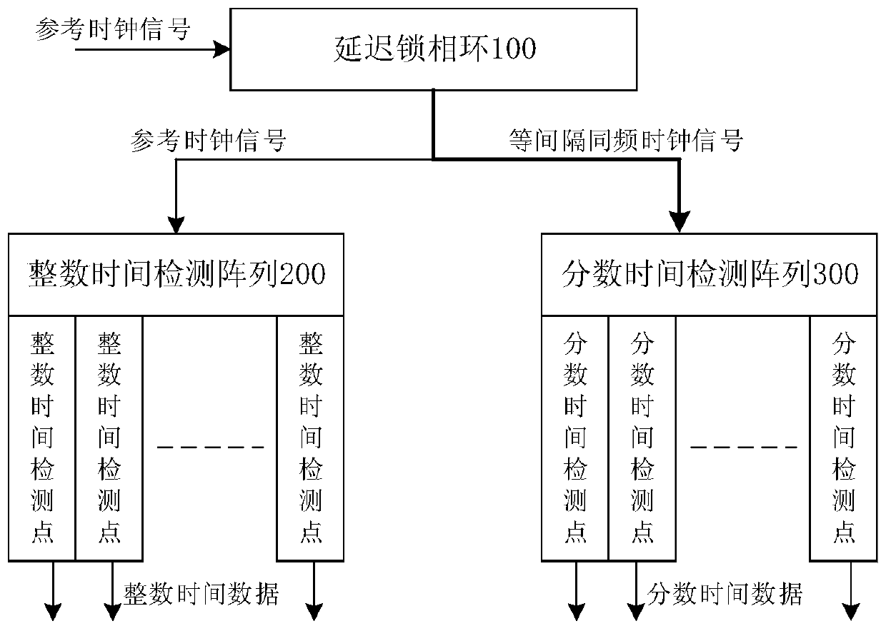
[0042] See figure 2 , figure 2 A schematic block diagram of a digital-to-time converter based on a delay-locked loop provided by an embodiment of the present invention includes: a delay-locked loop 100 and a TDC measurement part, wherein,

[0043] The delay-locked loop 100 receives the reference clock signal, delays the reference clock signal to generate an equally spaced co-frequency clock cluster signal, and outputs the reference clock signal and the equally spaced co-frequency clock cluster signal;

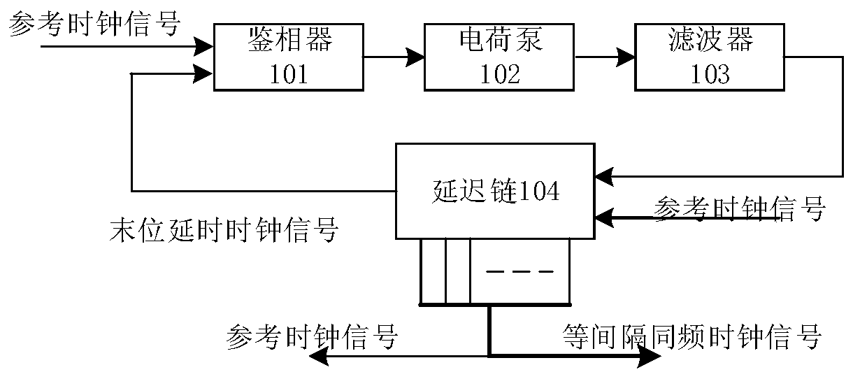
[0044] Further, see image 3 , image 3It is a schematic diagram of a module of a delay-locked loop provided by an embodiment of the present invention. The delay-locked loop 100 is composed of a phase detector 101, a charge pump 102, a filter 103 and a delay chain 104; the phase detector 100 receives the reference clock signal and Delay the clock signal (for example, the delayed clock signal is delayed by one clock cycle), compare the phases of the reference clock signal a...


PUM


Abstract

The invention relates to a time-to-digital converter based on a delay phase-locked loop. The converter comprises the delay phase-locked loop, an integer time detection array and a fractional time detection array, wherein the delay phase-locked loop is used to receive a reference clock signal, delay the reference clock signal to generate an equal-interval co-frequency clock cluster signal, and output the reference clock signal and the equal-interval co-frequency clock cluster signal; the integer time detection array is connected to the delay phase-locked loop and is used for receiving the reference clock signal, counting the reference clock signal, and outputting integer time data; and the fractional time detection array is connected to the delay phase-locked loop and is used for receivingthe equal-interval co-frequency clock cluster signal, a start signal and a stop signal, quantifying the start signal and the stop signal taking the equal-interval co-frequency clock cluster signal asa reference and outputting fractional time data. By using the time-to-digital converter, the accuracy and the stability of measurement are increased, the anti-interference capability of TDC is improved, the complex degree of a decoding circuit is simplified and the power consumption area of the TDC is reduced.

Description

technical field [0001] The invention belongs to the technical field of laser radar optical signal receiver systems, in particular to a time-to-digital converter based on a delay phase locked loop. Background technique [0002] In 1960, the world's first laser came out, and in 1961 the laser was first used in the ranging system. Due to a series of excellent optical properties of lasers such as high collimation, high monochromaticity, high power density and high coherence, various ranging technologies for different scenarios and different ranges are constantly being introduced. From as small as the micron-scale range close to the laser wavelength, centimeter-scale object shapes and target object distances from several kilometers to tens of kilometers, as large as the distance between the earth and satellites and even the moon, lasers can be used to accurately measure. And with the development of science and technology, the application scope of lidar is more and more extensive...

Claims


Application Information

Patent Timeline
Patent Type & Authority Patents(China)
IPC IPC(8): G04F10/00H03L7/081H03L7/18
CPCG04F10/005H03L7/0814H03L7/18
Inventor 丁瑞雪郝康马瑞孙德鹏张玮朱樟明杨银堂
Owner XIDIAN UNIV
Features
  • R&D
  • Intellectual Property
  • Life Sciences
  • Materials
  • Tech Scout
  • Unparalleled Data Quality
  • Higher Quality Content
  • 60% Fewer Hallucinations
Learn More