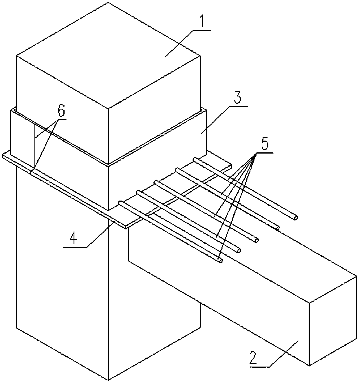
Steel joint for reinforcing and anchoring concrete beam and anchoring method

A technology for concrete beams and steel joints, which is used in construction, building maintenance, building construction, etc., can solve the problems of large damage to the original structure, large holes in the planting reinforcement, and large structural damage, so as to ensure construction quality, improve production efficiency, The effect of low installation difficulty

Inactive Publication Date: 2019-03-29
BEIJING ACAD OF BUILDING ENG +1
View PDF11 Cites 2 Cited by
  • Summary
  • Abstract
  • Description
  • Claims
  • Application Information

AI Technical Summary

Problems solved by technology

[0005] (3) Due to the introduction of new codes, the built buildings designed according to the old codes cannot meet the requirements of the existing codes and need to be reinforced
[0010] (1) The number of planted bars is large, and the planted bars have many holes, which will cause great damage to the original structure and be unfavorable to the original structure;
[0011] (2) The diameter of the steel bar is large, and the hole for planting the bar is large, which will cause great damage to the original structure and be unfavorable to the original structure;
[0012] (3) The anchoring length is long, the reinforcement hole is deep, the drilling is difficult, the damage to the original structure is great, and it is unfavorable to the original structure
And if the anchorage length is not enough, it will lead to the failure of the anchorage of the newly added longitudinal reinforcement, and the effect of reinforcement will not be achieved.

Method used


Image

  • Steel joint for reinforcing and anchoring concrete beam and anchoring method

Examples


Embodiment Construction

[0034] The following will clearly and completely describe the technical solutions in the embodiments of the present invention with reference to the accompanying drawings in the embodiments of the present invention. Obviously, the described embodiments are only some, not all, embodiments of the present invention. Based on the embodiments of the present invention, all other embodiments obtained by persons of ordinary skill in the art without making creative efforts belong to the protection scope of the present invention.

[0035] The object of the present invention is to provide a steel node and anchoring method for reinforcing and anchoring concrete beams, so as to solve the problems in the prior art mentioned above, make the construction simple, the newly added longitudinal steel bars are reliable in anchoring, have little damage to the original structure, and have strong applicability.

[0036] In order to make the above objects, features and advantages of the present inventio...


PUM


Abstract

The invention discloses a steel joint for reinforcing and anchoring a concrete beam. The steel joint comprises a concrete column of an original structure and the to-be-reinforced beam, the concrete column of the original structure is sleeved with a horizontal ring plate and a ring hoop plate, the ring hoop plate is arranged on the horizontal ring plate, one end of the horizontal ring plate is located on the to-be-reinforced beam, and a plurality of newly-arranged longitudinal reinforcing steel bars are connected to the side, close to the to-be-reinforced beam, of the ring hoop plate. The invention further discloses an anchoring method of the steel joint for reinforcing and anchoring the concrete beam. The method comprises the steps of determining the sizes of the outer profiles of the ringhoop plate and the horizontal ring plate; determining the strength grade and thickness of steel of the ring hoop plate and the horizontal ring plate; establishing a finite element analysis model of the steel joint; producing the steel joint in a machining factory, reserving two splicing welding joints, and conducting welding after on-site splicing is completed; splicing and welding the steel joint on site, and pouring structural glue between the steel joint and the concrete column of the original structure. By means of the steel joint for reinforcing and anchoring the concrete beam and the anchoring method, the construction is convenient, the newly-arranged longitudinal reinforcing steel bars are stably anchored, the damage to the original structure is small, and the applicability is high.

Description

technical field [0001] The invention relates to the technical field of concrete beam reinforcement, in particular to a steel node for reinforcement and anchorage of concrete beams and an anchoring method. Background technique [0002] In recent years, there have been more and more projects to reinforce existing buildings for the following reasons. [0003] (1) Buildings that are about to reach the design service life (generally 50 years), such as a large number of reinforced concrete industrial and civil buildings built since the 1950s and 1960s. These houses have been in use for 40 to 50 years. Due to durability problems such as disrepair, the original structure of this type of building has insufficient bearing capacity and endangers the safety of the structure. Reinforcement is required to ensure safe use; [0004] (2) Although the original structure is far from the designed service life, and there are no problems in durability and safety, the original structure needs to ...

Claims


Application Information

Patent Timeline
Patent Type & Authority Applications(China)
IPC IPC(8): E04G23/02
CPCE04G23/0218
Inventor 张开臣李铭车英明张晓迪李勃郑粤李颖杰彭博张慧颖秘红丹王泽强兰春光
Owner BEIJING ACAD OF BUILDING ENG
Why Eureka
Try Eureka