Redundant driving underwater gate valve executing mechanism

An actuator, driving water technology, applied in the direction of engine components, valve details, valve devices, etc., can solve problems such as maintenance difficulties, affecting the normal production of underwater oil and gas fields, etc., to ensure sealing performance, reduce the risk of sticking, and avoid pressure. Effect

Active Publication Date: 2019-03-29
NO 719 RES INST CHINA SHIPBUILDING IND
View PDF9 Cites 7 Cited by
  • Summary
  • Abstract
  • Description
  • Claims
  • Application Information

AI Technical Summary

Problems solved by technology

The patent document with the application number CN201611021928.3 proposes a high-reliability hydraulic underwater gate valve, but the hydraulic drive and screw drive of the device are not completely independent, and the piston will be linked in the hydraulic cylinder when the screw drive is used to open and close the gate valve , it is necessary to keep the oil port of the hydraulic cylinder unblocked to ensure that the hydraulic cylinder absorbs and returns oil without holding the pressure and making it impossible to open and close the gate valve
Moreover, the existing underwater gate valve actuator has the following problems: the underwater gate valve actuator works in the subsea oil production system, and it is very difficult to repair when it fails, and the oil production system needs to be shut down to cooperate with maintenance, which seriously affects the normal production of underwater oil and gas fields. The reliability of the lower gate valve actuator puts forward higher requirements; as the water depth increases, the external pressure continues to increase, requiring the underwater gate valve actuator to withstand higher external pressure; the opening of the high-pressure underwater gate valve requires the gate valve actuator to have greater output force

Method used


Image

  • Redundant driving underwater gate valve executing mechanism
  • Redundant driving underwater gate valve executing mechanism
  • Redundant driving underwater gate valve executing mechanism

Examples


Embodiment Construction

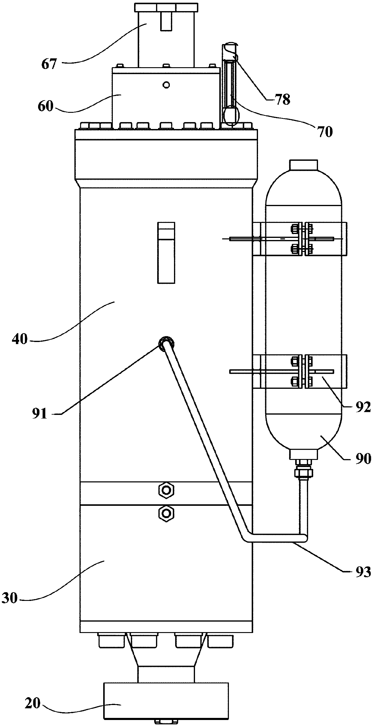
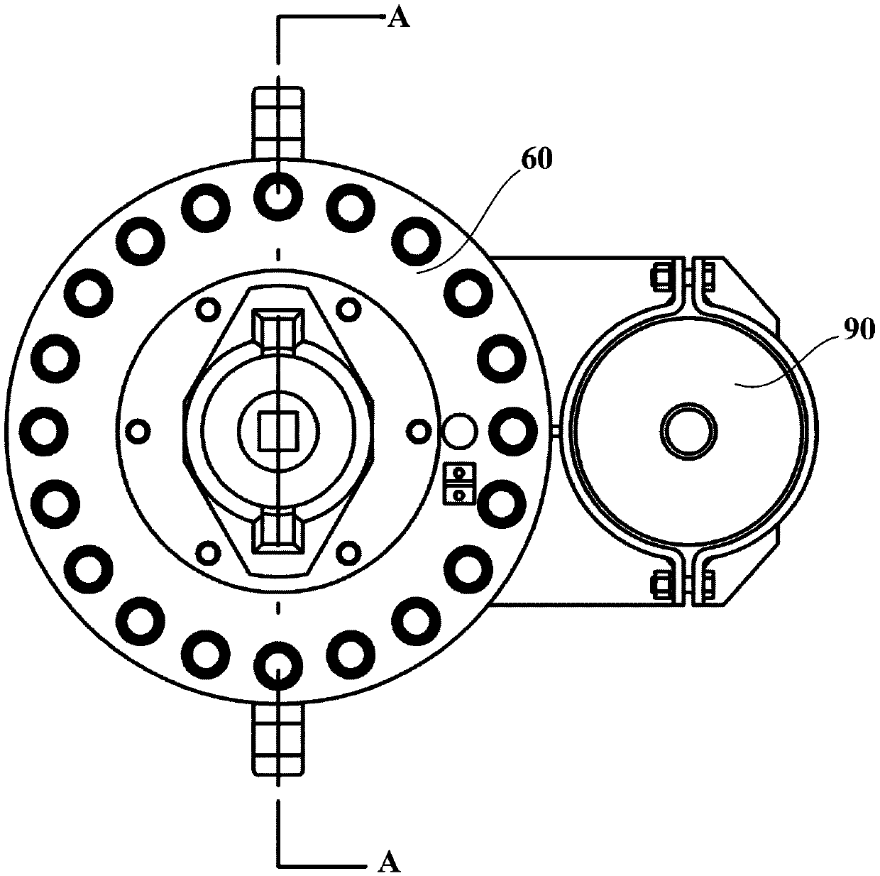
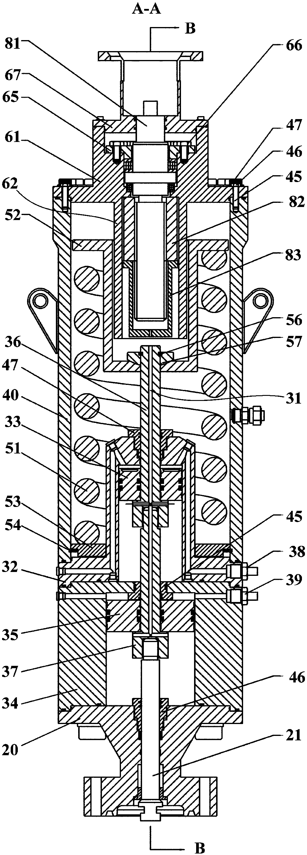
[0043] figure 1 It is a schematic front view of a redundantly driven underwater gate valve actuator according to an embodiment of the present invention. Such as figure 1 shown, and refer to Figure 2 to Figure 4 , the embodiment of the present invention provides a redundantly driven underwater gate valve actuator. The redundantly driven underwater gate valve actuator includes a valve body end cover 20, a valve stem 21 that can move up and down through the valve body end cover 20 and is sealingly connected with the valve body end cover 20, a hydraulic drive device 30, and a mechanism housing. Body 40 , reset assembly 50 , upper end cover 60 , valve stem position indicating assembly 70 , ROV driving device 80 and pressure compensator 90 .

[0044] The hydraulic drive device 30 is connected to the valve body cover 20 and has a piston rod, at least one cylinder and at least one piston. Each piston is located within a cylinder. The lower end of the piston rod is fixedly connecte...


PUM


Abstract

The invention provides a redundant driving underwater gate valve executing mechanism. The redundant driving underwater gate valve executing mechanism comprises a hydraulic driving device, wherein a piston and a piston rod are arranged to drive the piston rod to move downwards when the piston moves downwards, and the piston rod is separated from the piston when the piston rod moves downwards; a ROVdriving device is provided with a threaded shaft, a transmission nut and a sleeve; the transmission nut and the sleeve can move up and down in the sleeve, the sleeve is located on the lower side of the transmission nut, and the lower end of the sleeve is a contact plate for enabling the upper end of the piston rod to be in contact abutting against the upper end of the piston rod; the threaded shaft is rotationally arranged on the upper cover part and is matched with the transmission nut; and a pressure compensator is arranged on a mechanism shell through a support, and the pressure compensator is connected with a pressure compensation joint through a compensation oil pipe so as to communicate with the inner part of the mechanism shell. The two structures of hydraulic driving and ROV operation can be separated independently, and under the action of deep sea high pressure, the dynamic balance of the outer pressure inside the mechanism shell can be guaranteed.

Description

technical field [0001] The invention relates to the field of deep sea oil and gas field development, in particular to a redundantly driven underwater gate valve actuator. Background technique [0002] Subsea gate valve is a key component of offshore oil and gas field Christmas tree and subsea manifold, and plays an important role in subsea oil production system. The underwater gate valve actuator is a driving device that can drive the underwater gate valve to the fully open or fully closed position, or control the opening of the underwater gate valve according to instructions. The existing underwater gate valve actuators mostly adopt hydraulic drive, electric drive, ROV operation or compound operation. However, the existing composite underwater gate valve actuators need two kinds of drives to cooperate with each other or the other drive is in a designated state to complete the action of opening and closing the gate valve, and the fully independent redundant drive has not be...

Claims


Application Information

Patent Timeline
Patent Type & Authority Applications(China)
IPC IPC(8): F16K31/122F16K31/50F16K37/00
CPCF16K31/1221F16K31/50F16K37/0008
Inventor 景满军向超陆锦锦毋迪姜勇
Owner NO 719 RES INST CHINA SHIPBUILDING IND
Why Eureka
Try Eureka