Biofertilizer cooling device

A cooling device and bio-fertilizer technology, applied in heat exchange equipment, direct contact heat exchangers, heat exchanger types, etc., can solve problems such as low work efficiency, external cold and internal heat, limited cooling area of ​​fertilizers, etc., and achieve improved The effect of the cooling effect

Pending Publication Date: 2019-03-29
安徽金秋肥业有限公司
View PDF0 Cites 3 Cited by
  • Summary
  • Abstract
  • Description
  • Claims
  • Application Information

AI Technical Summary

Problems solved by technology

[0005] The production of biological fertilizer needs to go through the processing process of batching→mixing→granulation→drying→cooling→sieving→packaging. During the cooling process, due to the large amount of biological fertilizer, the cooling device cools the fertilizer in the box through the cooling fan. The cold air blown

Method used


Image

  • Biofertilizer cooling device
  • Biofertilizer cooling device
  • Biofertilizer cooling device

Examples


Embodiment 1

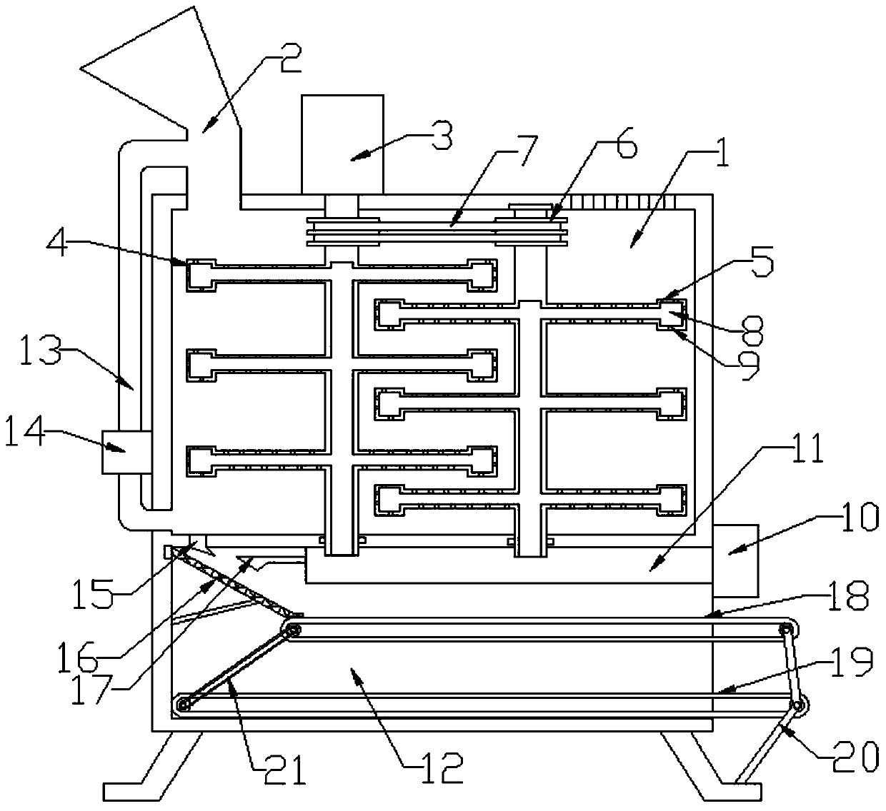
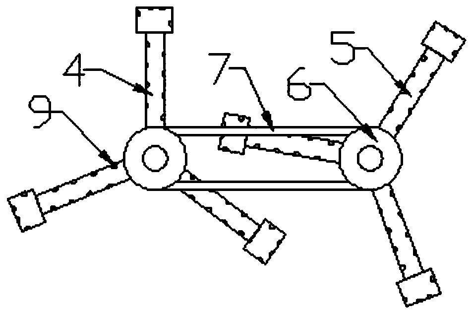
[0028] Such as Figure 1-4 As shown, a biological fertilizer cooling device includes a cooling box 1, a discharging box 12, a stirring cooling system composed of a servo motor 3, a main agitator 4, a sub-agitator 5 and a cooler 10, a feeding pipe 13 and a feeding pump 14 A feeding and mixing system composed of an inclined vibrating screen 16, a first conveyor belt 18, and a second conveyor belt 19 is a screening and discharging system. The bottom of the discharging box 12 is welded with a discharging box 12, and the discharging box 12 passes through its bottom. Supported by a support column welded at the ends, a feed hopper 2 is connected to the top side of the cooling box 1 and a discharge port is provided on one side of the discharge box 12.

[0029] The servo motor 3 in the mixing cooling system is fixed on the top of the cooling box 1 by bolts, and the output end of the servo motor 3 is also connected to the main agitator 4, the auxiliary agitator 5 and the main agitator 4 in...

Embodiment 2

[0033] Such as Figure 1-4 As shown, the feeding pipe 13 in the feeding mixing system is connected below one side of the cooling box 1, the feeding pump 14 is installed on the feeding pipe 13, and the tail end of the feeding pipe 13 is connected to the feeding hopper 2 for connecting the cooling box The fertilizer cooled in 1 is mixed with the original fertilizer in the feeding hopper 2, and then sent to the cooling box 1 for mixing and cooling.

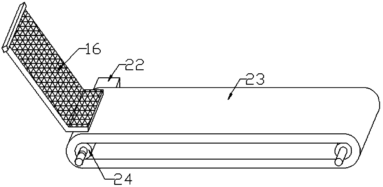
[0034] In the screening and discharging system, the material guide port 15 provided at the bottom end of the cooling box 1 is connected to the discharge box 12, and an inclined vibrating screen 16 is installed below the material guide port 15, and the air outlet hopper 17 connected to the top of the air pipe 11 is directly inclined. The vibrating screen 16 is used to cool the fertilizer on the inclined vibrating screen 16. The end of the inclined vibrating screen 16 is connected to the first conveyor belt 18, and a second conveyor belt ...


PUM


Abstract

The invention discloses a biofertilizer cooling device which comprises a stirring and cooling system composed of a cooling box, a discharging box, a servo motor, a main stirrer, an auxiliary stirrer and an air cooler, a feeding and mixing system composed of a feeding pipe and a feeding pump, and a screening and discharging system composed of an inclined vibrating screen, a first conveyor belt anda second conveyor belt. The discharging box is welded to the bottom end of the discharging box, and a feeding hopper communicates to one side of the top end of the cooling box. The cooling device stirs and mixes a fertilizer through double stirrers, cold air blown by the air cooler is exported through an air outlet hole and is fed into the fertilizer along with rotation of the stirrers to cool thefertilizer from inside to outside, the fertilizer exported from a material guide port is pre-screened by the inclined vibrating screen, and two fertilizers of different levels are fed to different positions through the first conveyor belt and the second conveyor belt to be screened again. In the pre-screening process, an air outlet hopper is aligned to the inclined vibrating screen to blow cold air to cool the fertilizer thereon again.

Description

Technical field [0001] The invention relates to the technical field of biological fertilizer production equipment, in particular to a biological fertilizer cooling device. Background technique [0002] Existing biological fertilizers are all based on organic matter, and then mixed with bacteria and inorganic fertilizers. In order to widely improve this general and traditional situation, bio-fertilizer products go far beyond the existing concept. It will be expanded to not only provide crop nutrition, but also improve the soil; at the same time, it should also disinfect the soil, that is, use organisms (mainly microorganisms) to decompose and eliminate pesticides (insecticides and fungicides), herbicides, and Pollutants from products such as petrochemicals, and at the same time play a role in repairing the soil. [0003] Biological fertilizer in a narrow sense refers to microbial (bacterial) fertilizer, referred to as bacterial fertilizer, and also known as microbial inoculant. I...

Claims


Application Information

Patent Timeline
IPC IPC(8): F28C3/12F28F5/04
CPCF28C3/12F28F5/04
Inventor 陈永芳
Owner 安徽金秋肥业有限公司
Why Eureka
Try Eureka