
Time domain stacking surface wave detection method based on pseudo random signals

A pseudo-random signal and detection method technology, which is applied in the field of time-domain superimposed surface wave detection based on pseudo-random signals, can solve the problems of slow deployment time, extremely high coordinate requirements, and application limitations, and achieve improved observation efficiency and high detection accuracy , good consistency

Active Publication Date: 2019-03-29
YELLOW RIVER ENG CONSULTING
View PDF19 Cites 0 Cited by
  • Summary
  • Abstract
  • Description
  • Claims
  • Application Information

AI Technical Summary

Problems solved by technology

[0004] In terms of transient surface waves, general explosives are no longer used in surface wave detection, while the effective depth of hammering surface wave detection technology is generally less than 30m, especially in soil layers. The effective depth is generally less than 20m, and the related frequency dispersion spectrum is wide. As a result, the depth and velocity pickup is very unstable, and its application in engineering is greatly limited
[0005] In terms of natural source surface wave technology, although the detection depth is relatively large, the arrangement of the observation system is complex and generally requires a three-dimensional arrangement. This arrangement requires extremely high coordinates, and the arrangement time is relatively slow, which requires a high observation time.
The natural source surface wave detection at a point generally takes more than 1 hour, and this arrangement is not satisfactory in most sites
If quasi-linear arrangement and other methods are used, there are certain errors in the speed of acquisition in theory and practice, which lead to the inability of large-scale promotion of this technology in the actual engineering survey and quality inspection application process

Method used


Image

  • Time domain stacking surface wave detection method based on pseudo random signals

Examples


Embodiment Construction

[0019] The embodiments of the present invention will be described in detail below in conjunction with the accompanying drawings. This embodiment is implemented on the premise of the technical solution of the present invention, and detailed implementation methods and specific operating procedures are provided, but the scope of protection of the present invention is not limited to the following Described embodiment.

[0020] The time-domain superposition surface wave detection method based on the pseudo-random signal of the present invention is carried out according to the following steps:

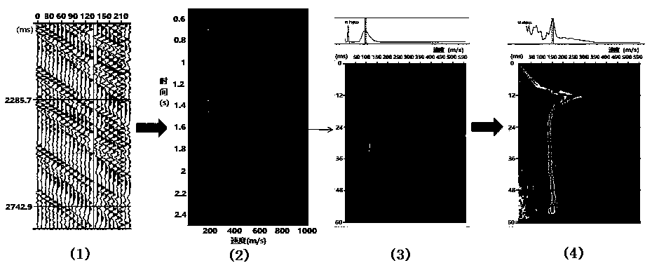
[0021] step 1, figure 1 As shown in (1), in order to obtain a pseudo-random signal, this signal must first be directional, and secondly, it is best to distribute the whole frequency band or the frequency band range is between 1Hz-1000Hz. There are various ways to obtain the pseudo-random signal, which can be the vibration noise of the car (such as Shenzhen Qianhai Geophysical Prospecting Wo...


PUM


Abstract

The invention discloses a time domain stacking surface wave detection method based on pseudo random signals. The method comprises the steps of: the step 1, obtaining pseudo random signals, wherein theobtained pseudo random signals must have the directionality and are in full spectrum band distribution or in a spectrum band range of 1Hz-1000Hz, and the mode of obtaining the pseudo random signals is that vehicle vibration noise, vibration noise of a river with a flow speed larger than 2m / s or vibration noise loaded by manual operation; the step 2, performing t-p transform of the obtained pseudorandom signals to obtain time-speed domain signals; and the step 3, performing overlapping of the obtained time-speed domain signals in the time-speed domain, namely performing Fourier transform onceat the time domain to transform the time domain to a frequency domain to obtain frequency-speed domain signals. The time domain stacking surface wave detection method has the advantages of high detection precision and good consistency, at the same point, the speeds obtained by testing at different times have an error of less than 10%, the precision is very high, and therefore the time domain stacking surface wave detection method can be used as an effective testing method for testing.

Description

technical field [0001] The invention relates to engineering survey and non-destructive inspection of engineering quality, in particular to a time-domain superimposed surface wave detection method based on pseudo-random signals. Background technique [0002] In engineering survey and non-destructive testing of engineering quality, wave velocity is a very important and very stable parameter. The characterization of geological structure and the characterization of the target body are less affected by external interference, and the obtained signal is stable. It is an important parameter. Detection and detection means. Especially in the non-destructive testing of engineering quality, the speed is not greatly changed by the external climate, environment and other factors. Therefore, if the speed of related projects does not change within a certain period of time, the speed is stable. Therefore, the speed is used to evaluate the quality of the project It is also an important detec...

Claims


Application Information

Patent Timeline
Patent Type & Authority Applications(China)
IPC IPC(8): G01N29/04G01N29/36G01N29/46
CPCG01N29/04G01N29/36G01N29/46G01N2291/011G01N2291/0289G01N2291/0423
Inventor 姜文龙马若龙谢向文郭玉松刘现锋毋光荣
Owner YELLOW RIVER ENG CONSULTING
Learn More