
Maskless projection lithography system

A projected light, maskless technology, applied in microlithography exposure equipment, optics, photography, etc., can solve problems affecting the exposure stability of the optical system, reduce edge diffraction, and improve quality

Inactive Publication Date: 2019-04-02
深圳市纳姆达科技有限公司
View PDF3 Cites 2 Cited by
  • Summary
  • Abstract
  • Description
  • Claims
  • Application Information

AI Technical Summary

Problems solved by technology

It should also be emphasized that this method requires the introduction of a rotating mechanism, and the movement of this mechanism will generate a certain degree of vibration, which will affect the exposure stability of the entire optical system

Method used


Image

  • Maskless projection lithography system
  • Maskless projection lithography system
  • Maskless projection lithography system

Examples


Embodiment Construction

[0027] The following will clearly and completely describe the technical solutions in the embodiments of the present invention with reference to the accompanying drawings in the embodiments of the present invention. Obviously, the described embodiments are only some of the embodiments of the present invention, not all of them. Based on the embodiments of the present invention, all other embodiments obtained by persons of ordinary skill in the art without making creative efforts belong to the protection scope of the present invention.

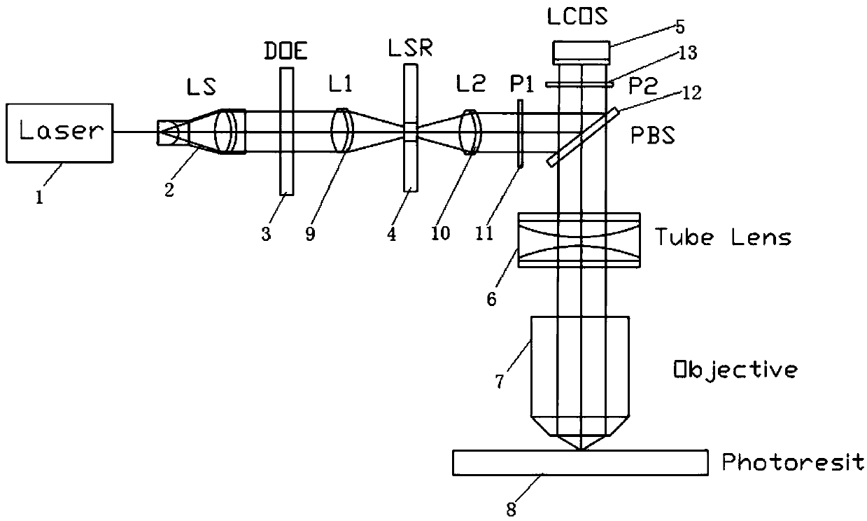
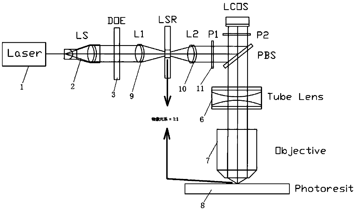
[0028] see Figure 1-4, a maskless projection lithography system, including Laser laser 1, LS collimator lens group 2, DOE diffractive optical element 3, LSR laser speckle attenuator 4, LCOS reflective liquid crystal spatial light modulator 5, Tube Lens tube Lens 6, Objective infinity conjugate microscope objective lens 7 and Photoresist photoresist plate 8; the beam exit of Laser laser 1 and the center of LS collimating lens group 2 are located ...


PUM


Abstract

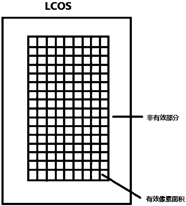
The invention discloses a maskless projection lithography system. The maskless projection lithography system comprises a Laser, an LS collimating lens group, a DOE (diffractive optical element), an LSR laser speckle attenuator, an LCOS reflective liquid crystal spatial light modulator, a Tube Lens, an Objective infinity conjugate microscope, a Photoresist photolithography plate, a L1 lens, a L2 lens, a P1 polarizing element and a P2 polarizing element; a laser is transmitted to the LS collimating lens group, the DOE, the L1 lens, the LSR laser speckle attenuator, the L2 lens, the P1 polarizingelement, a PBS polarization splitting prism, the LCOS reflective liquid crystal spatial light modulator, the P2 polarizing element, the Tube Lens, and the Objective infinity conjugate microscope andis finally projected and imaged on the Photoresist photolithography plate. Through control of the parameter designs of the DOE, the L1 lens and the L2 lens, the area of the collimation light irradiated on the LCOS is equal to the area of the effective pixel of the collimation light to fully utilize the light energy, effectively reduce the edge diffraction phenomenon and improve the projection andimaging quality.

Description

technical field [0001] The invention relates to the technical fields of MEMS chip fabrication, mask plate processing, DOE element fabrication and diffractive optical variable element fabrication, and in particular to a maskless projection lithography system. Background technique [0002] Because the laser has the characteristics of good collimation and high energy density, coupled with the widespread use of lasers in recent years, most of the maskless lithography systems use lasers as illumination sources. However, the laser itself also has the disadvantages of Gaussian energy distribution and speckle noise. [0003] The existing methods to homogenize laser illumination and attenuate speckle noise are as follows: [0004] (1) Optical integrator-uniform light tube: The principle of uniform light is that light is reflected multiple times in the uniform light tube, each reflection will form a virtual light source image, and multiple reflections form a two-dimensional virtual l...

Claims


Application Information

Patent Timeline
Patent Type & Authority Applications(China)
IPC IPC(8): G03F7/20
CPCG03F7/70258G03F7/70383
Inventor 游剑锋李建兵陈国华
Owner 深圳市纳姆达科技有限公司
Learn More