Method for calibrating a pinhole camera by using a public autopolar triangle and an orthogonal vanishing point of a separation circle

A pinhole camera and vanishing point technology, applied in the field of computer vision, can solve problems such as errors, redundant straight lines, and inability to directly obtain images of ring points, and achieve the effects of simple production, improved accuracy, and improved calibration accuracy.

Inactive Publication Date: 2019-04-02
YUNNAN UNIV
View PDF2 Cites 6 Cited by
  • Summary
  • Abstract
  • Description
  • Claims
  • Application Information

AI Technical Summary

Problems solved by technology

The document "An algorithm for self-calibration from several views", (R. Hartley., In Proc. IEEE Conference on Computer Vision and Pattern Recognition, pages 908–912, June 1994.) proposed a pinhole camera self-calibration method, The advantage of this type of method is that there is no need to use a calibration block, and the disadvantage is that the corresponding points between images must be obtained
In computer vision, it is very difficult to implement a very effective method for finding corresponding points.
The literature "A new easy camera calibration technique based on circular points", (Meng, X., Hu, Z., Pattern Recognition, 2003, 36(5): 1155-1164.) proposes to use a circle and pass through a pinhole camera Several branch lines at the center of the circle are used as calibration templates. The advantage of this method is that the vanishing point can be obtained by linear solution, but the image of the circle point cannot be directly obtained, and there will be redundant straight lines, resulting in greater error

Method used


Image

  • Method for calibrating a pinhole camera by using a public autopolar triangle and an orthogonal vanishing point of a separation circle
  • Method for calibrating a pinhole camera by using a public autopolar triangle and an orthogonal vanishing point of a separation circle
  • Method for calibrating a pinhole camera by using a public autopolar triangle and an orthogonal vanishing point of a separation circle

Examples


Embodiment

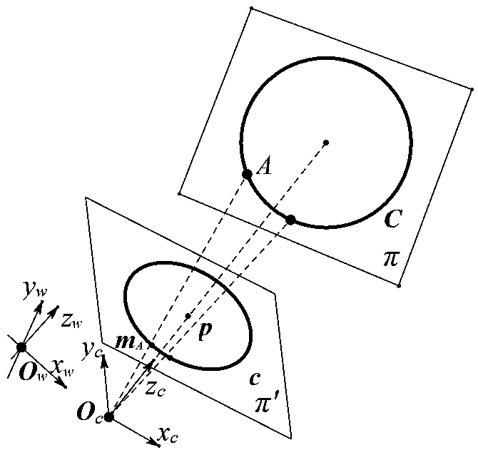
[0053] The invention proposes a method for linearly determining internal parameters of a pinhole camera using a plane space separation circle as a target. The experimental template structural schematic diagram that the present invention adopts is as figure 2 shown. The implementation of the present invention will be described in more detail with an example below.

[0054] The experimental template used in the calibration of pinhole cameras based on the separation circle in space is the separation circle on the plane. Utilize the method in the present invention to calibrate the pinhole camera, the specific steps are as follows:

[0055] 1. Fit image boundary and target curve equation

[0056] The image size used in the present invention is 1038×1048. Take 6 images of the target with a pinhole camera and read in the images. Use the Edge function in Matlab to extract the pixel coordinates of the edge points of the target image, and use the least square method to fit the equ...


PUM


Abstract

The invention relates to a method for calibrating a pinhole camera by using a public autopolar triangle and an orthogonal vanishing point of a separation circle. Firstly, edge points of a target imageare extracted from the image, and a circular image equation is obtained through least square method fitting. According to the fact that any two separated circular images have a unique public self-polar triangle, a group of corresponding poles and polar lines of the pair of separated circular images can be obtained. Meanwhile, the polar line is an image passing through the circle centers of the two circles, and the polar point is a vanishing point. Wherein the vanishing point has a polar line relative to the separated circle image, the polar line passes through the image of the circle center and the circle image and is intersected with the two points, the image of the circle center and the vanishing point in the polar line direction can be obtained by utilizing the property of harmonizingand conjugating the two intersected points and the image of the circle center, and the obtained two vanishing points are a group of orthogonal vanishing points. Therefore, six groups of orthogonal vanishing points can be obtained from the six images, and the internal parameters of the pinhole camera are solved by using the constraint of the orthogonal vanishing points and the image of the absolutequadratic curve.

Description

technical field [0001] The invention belongs to the field of computer vision, and relates to a method for solving internal parameters of a pinhole camera by using a common self-polar triangle and an orthogonal vanishing point of a separating circle on a plane. Background technique [0002] The central task of computer vision is to understand images, and its ultimate goal is to enable computers to have the ability to recognize three-dimensional environmental information through two-dimensional images. This ability will not only enable the machine to perceive the geometric information of objects in a three-dimensional environment including shape, posture, motion, etc., but also describe, store, recognize and understand them. Camera calibration is to determine the mapping relationship from a three-dimensional space point to its two-dimensional image point, which is an essential step in many computer vision applications. In order to determine this mapping process, it is necessa...

Claims


Application Information

Patent Timeline
Patent Type & Authority Applications(China)
IPC IPC(8): G06T7/80
CPCG06T7/80
Inventor 汪雪纯杨丰澧赵越
Owner YUNNAN UNIV
Why Eureka
Try Eureka