Metal-carbon particle composite material and method for manufacturing same

A technology of composite materials and carbon particles, which is applied in the direction of metal layered products, chemical instruments and methods, cooling/ventilation/heating transformation, etc., can solve problems such as sintering of difficult composites, inconsistent joint interfaces, insufficient joints, etc., to achieve High cooling reliability, easy thickness, and high heat dissipation effect

Inactive Publication Date: 2019-04-02
RESONAC HOLDINGS CORPORATION
View PDF14 Cites 0 Cited by
  • Summary
  • Abstract
  • Description
  • Claims
  • Application Information

AI Technical Summary

Problems solved by technology

In this method, it is difficult to sinter the composite body, so it is considered that the bonding is insufficient and the mismatch of the bonding interface is likely to occur.

Method used


Image

  • Metal-carbon particle composite material and method for manufacturing same
  • Metal-carbon particle composite material and method for manufacturing same
  • Metal-carbon particle composite material and method for manufacturing same

Examples


Embodiment Construction

[0051] Next, some embodiments of the present invention will be described below with reference to the drawings.

[0052] Figure 1~5 It is a figure for demonstrating the metal-carbon particle composite material and its manufacturing method of 1st Embodiment of this invention.

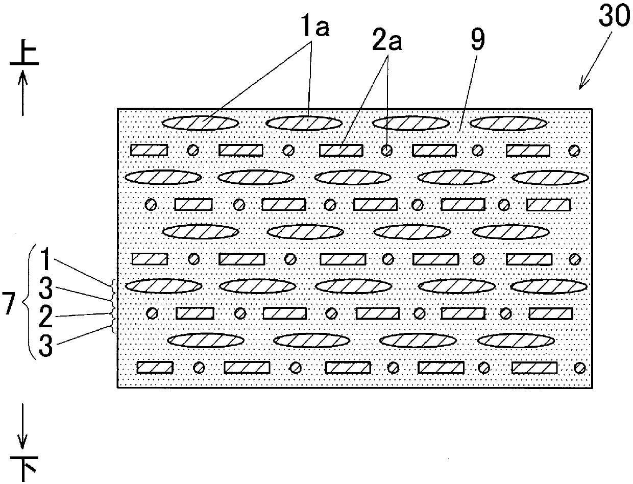
[0053] Such as figure 1 As shown, the metal-carbon particle composite material 30 of the first embodiment includes one or more scaly graphite particle dispersion layers 1, one or more carbon fiber dispersion layers 2, and one or more metal layers 3 in a laminated form. The graphite particle dispersion layer 1 is obtained by dispersing the scaly graphite particles 1a as carbon particles in a metal matrix (shown by hatching) 9, and the carbon fiber dispersion layer 2 is obtained by dispersing carbon fibers 2a as carbon particles in the metal matrix 9. Yes, the metal layer 3 is formed by the metal base 9.

[0054] In addition, one or more flaky graphite particle dispersion layers 1 , one or more carbon f...


PUM

PropertyMeasurementUnit
particle sizeaaaaaaaaaa
lengthaaaaaaaaaa
aspect ratioaaaaaaaaaa

Abstract

In a metal-carbon particle composite material (30), one or more flake-graphite-particle dispersion layers (1) in which flake graphite particles (1a) as carbon particles are dispersed in a metal matrix(9), one or more carbon fiber dispersion layers (2) in which carbon fibers (2a) as carbon particles are dispersed in the metal matrix (9), and one or more metal layers (3) formed in the metal matrix(9) are provided in layered fashion. The one or more flake-graphite-particle dispersion layers (1), the one or more carbon fiber dispersion layers (2), and the one or more metal layers (3) are joinedand integrated. Either the flake-graphite-particle dispersion layer (1) or the carbon fiber dispersion layer (2) and the metal layer (3) are arranged in a state of being layered in alternating fashionthroughout substantially the entire thickness direction of the composite material (30).

Description

technical field [0001] The present invention relates to a metal-carbon particle composite material comprising a metal matrix and carbon particles dispersed in the metal matrix, a manufacturing method thereof, and a cooler for power modules. [0002] Furthermore, in the scope of this specification and patent claims, unless otherwise specified, the term "aluminum" is used to include both pure aluminum and aluminum alloys. Unless otherwise specified, "copper The term "is used in a sense that includes both pure copper and copper alloys. [0003] In addition, the vertical direction of the metal-carbon particle composite material of the present invention is not limited. In the scope of this specification and patent claims, in order to easily understand the structure of the composite material, the thickness direction of the composite material and the thickness direction of the laminated body are defined separately. are the up-down direction of the composite material and the up-down ...

Claims


Application Information

Patent Timeline
Patent Type & Authority Applications(China)
IPC IPC(8): B32B15/01B05D7/14B05D7/24H01L23/36H01L23/373H05K7/20
CPCB32B15/01C22C47/20C22C49/14H01L23/373H01L23/3737H01L2224/32225B05D7/14B05D7/24B32B15/16B32B15/20B32B2255/06B32B2255/20B32B2264/108B32B2307/302H01L23/36H01L23/3735H05K7/20
Inventor 广濑克昌
Owner RESONAC HOLDINGS CORPORATION
Why Eureka
Try Eureka