
Light filter and sensor

A sensor and light filtering technology, applied in the direction of instruments, optics, scientific instruments, etc., can solve problems such as the influence of sensor detection accuracy

Inactive Publication Date: 2019-04-02
CAMBRIDGE DISPLAY TECH LTD +1
View PDF7 Cites 2 Cited by
  • Summary
  • Abstract
  • Description
  • Claims
  • Application Information

AI Technical Summary

Problems solved by technology

[0003] However, the detection accuracy of such sensors may be affected by the detection of light emitted from the light source

Method used


Image

  • Light filter and sensor
  • Light filter and sensor
  • Light filter and sensor

Examples


Embodiment

[0105] Measurement

[0106] The transmission spectra described herein were measured by casting a 0.7 mm thick film of filter compound onto a glass substrate and measuring the transmission using an Agilent Cary 5000 spectrophotometer, using a blank glass substrate as a reference.

[0107] Fluorescence spectra were measured as described herein using an Ocean Optics USB2000+ spectrometer using a 5 mW, 450 nm laser diode as the excitation source. Fluorescence is collected via a fiber optic cable connected to the spectrometer. Position the fiber to collect reflected fluorescence emission and use a long-pass filter to prevent laser light from entering the spectrometer.

[0108] Filter body embodiment 1-3: Tartrazine filter body

[0109] Formulations were prepared by dissolving tartrazine, 3,5-dinitrobenzoic acid and polyvinylpyrrolidone (PVP) in the amounts listed in Table 1 in a solvent of 50% by volume water and 50% by volume ethanol.

[0110] Table 1

[0111] Pre...

Embodiment 2

[0120] Filter Example 2: Formulation Example 1, 0.16ml / cm 2

Embodiment 3

[0121] Filter Example 3: Formulation Example 3, 0.33ml / cm 2

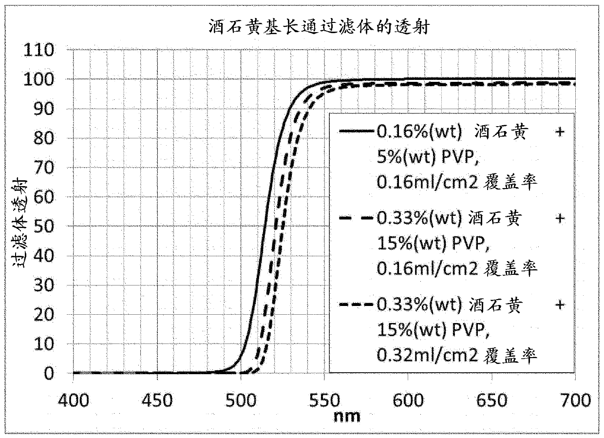
[0122] refer to figure 2 , Filter Examples 1-3 show high transmission below about 500 nm and high absorbance above about 550 nm. By choosing the concentration of the solution and / or the volume per unit area of ​​the solution deposited onto the substrate, the onset of the blocking band can be adjusted in the range of about 15-20 nm.

[0123] image 3 The transmission spectrum of filter example 1 is illustrated, superimposed with the fluorescence spectrum of sodium green.

[0124] Figure 4 The transmission spectrum of filter example 1 is illustrated, superimposed with the fluorescence spectrum of the sodium salt of fluorescein.


PUM

PropertyMeasurementUnit
wavelengthaaaaaaaaaa
thicknessaaaaaaaaaa
thicknessaaaaaaaaaa

Abstract

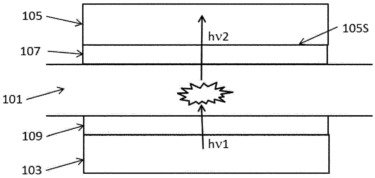
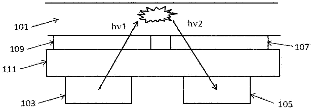
A sensor comprising a light source (103); a photodetector (105); a sample receptacle such as a microfluidic device (101) between the light source and the photodetector; and one or both of a first light filter (107) and a second light filter (109) wherein the first light filter is provided between the sample receptacle and the photodetector and the second light filter is provided between the samplereceptacle and the light source. The first light filter may comprise tartrazine. The second light filter may comprise Coomassie violet R200, Victoria Blue B or acid fuchsin. In use, light h[nu]1 emitted from the light source is absorbed by a luminescent indicator in the sample receptacle which then emits light h[nu]2 detected by the photodetector.

Description

field of invention [0001] The present invention relates to light filters and their use in sensors comprising light emitters and light detectors. Background technique [0002] Sensors that operate by illuminating a sample and detecting photoluminescence of luminescent markers in the sample are known, for example Williams et al, Electronics 2014, 3, 43-75 "Integration of Organic Light Emitting Diodes and Organic Photodetectors for Lab -on-a-Chip Bio-Detection Systems". [0003] However, detection accuracy of such sensors may be affected by detection of light emitted from a light source. [0004] Lefevre et al, Lab Chip, 2012, 12, 787–793 "Algal fluorescence sensor integrated into a microfluidic chip for water pollutant detection" discloses an organic light-emitting diode (OLED) and an organic photodetector (OPD) integrated into a microfluidic chip , the microfluidic chip is used to detect algae fluorescence in the microfluidic chamber of the chip. A luminescent filter is pr...

Claims


Application Information

Patent Timeline
Patent Type & Authority Applications(China)
IPC IPC(8): G01N21/64G02B5/22
CPCG01N21/645G02B5/22G01N2021/6471G01N21/64G02B5/223
Inventor J·博鲁格斯A·李J·博仁德特
Owner CAMBRIDGE DISPLAY TECH LTD
Learn More