A dual-series sintering system flue gas comprehensive circulation treatment method and treatment device

A technology for cyclic treatment and flue gas circulation, which is applied in gas treatment, separation methods, chemical instruments and methods, etc., can solve the problems of increased investment, increased energy consumption, and high environmental protection costs, so as to reduce operating costs, improve air environment, and reduce The effect of running costs

Active Publication Date: 2021-10-26
ZHONGYE-CHANGTIAN INT ENG CO LTD
View PDF8 Cites 0 Cited by
  • Summary
  • Abstract
  • Description
  • Claims
  • Application Information

AI Technical Summary

Problems solved by technology

Especially in the current dual-series sintering system, due to the large output, the amount of flue gas produced is also large, and the corresponding amount of harmful substances in the flue gas will increase. In this way, the cost of environmental protection will become higher and higher, and the investment will also increase. also increased

Method used


Image

  • A dual-series sintering system flue gas comprehensive circulation treatment method and treatment device
  • A dual-series sintering system flue gas comprehensive circulation treatment method and treatment device
  • A dual-series sintering system flue gas comprehensive circulation treatment method and treatment device

Examples


Embodiment 1

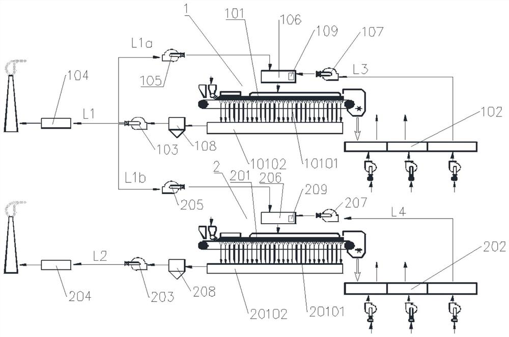
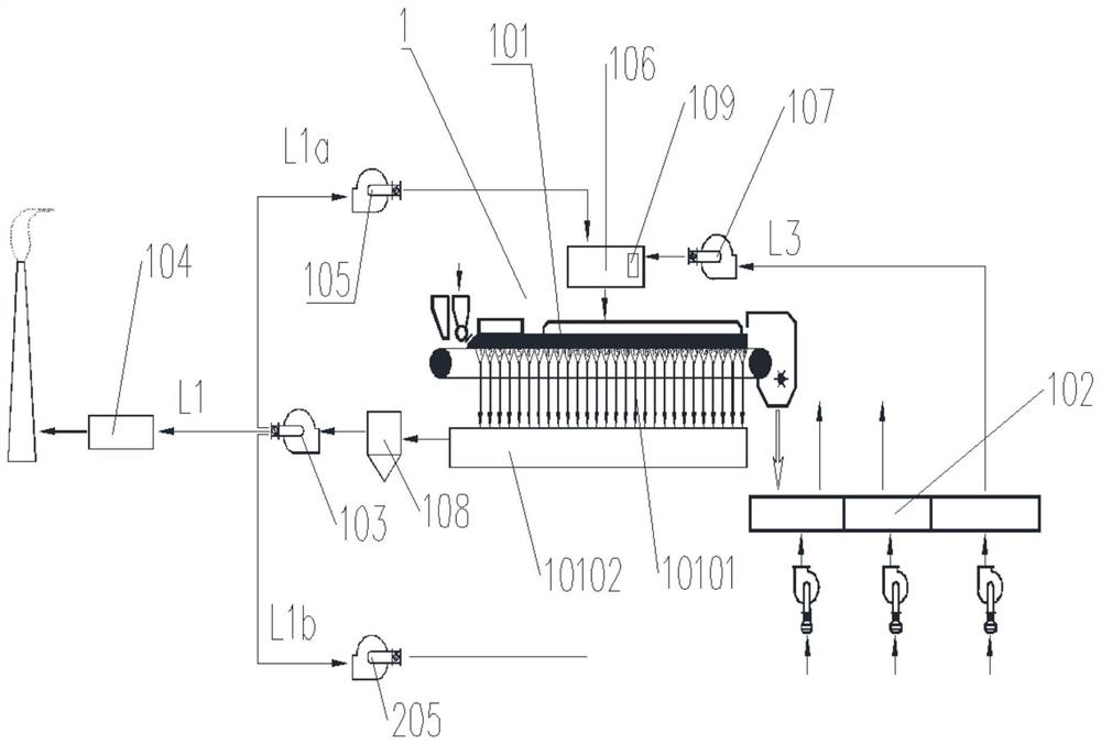
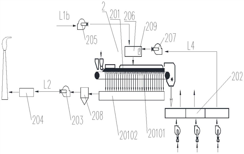
[0119] A dual-series sintering system flue gas comprehensive circulation treatment method, the sintering system includes A sintering system 1 and B sintering system 2, the method includes the following steps:

[0120] 1) Sintering process: The sintering material is loaded into the sintering machine in A sintering system 1 and B sintering system 2 respectively, and then the sintering material on the sintering machine is ignited and burned through the ignition furnace installed at the front of the sintering machine, and then introduced from the ring cooling The hot air of the machine is used for combustion-supporting sintering; the air above the sintering machine is drawn into the sintering material on the sintering machine independently by the main exhaust fan A103 of A sintering system 1 and the main exhaust fan B203 of B sintering system 2; The flue gas generated by the sintering machine enters the large flue A10102 in the A sintering system 1, and the flue gas generated by th...

Embodiment 2

[0128] Repeat Example 1, except that 60 (vol)% of the flue gas in the large flue A10102 is sent to the activated carbon desulfurization and denitrification system 104 . 20 (vol)% of the flue gas in the large flue A10102 is delivered to the flue gas circulation hood of the sintering machine A in the A sintering system 1 . 20 (vol)% of the flue gas in the large flue A10102 is delivered to the flue gas circulation hood of the sintering machine B in the B sintering system 2 .

Embodiment 3

[0130] Repeat Example 2, except that 70 (vol)% of the flue gas in the large flue A10102 is sent to the activated carbon desulfurization and denitrification system 104 . 15 (vol)% of the flue gas in the large flue A10102 is delivered to the flue gas circulation hood of the sintering machine A in the A sintering system 1 . 15 (vol)% of the flue gas in the large flue A10102 is delivered to the flue gas circulation hood of the sintering machine B in the B sintering system 2 .


PUM


Abstract

A dual-series sintering system flue gas comprehensive circulation method, the method comprises the following steps: 1) sintering process: raw materials are sintered in a sintering machine to generate sintering gas; 2) cooling process: the sintered raw materials are cooled in a ring cooler; 3 ) Flue gas treatment: After passing through the dust removal device, the sintering gas enters the desulfurization and denitrification system for treatment. The A sintering system adopts the activated carbon desulfurization and denitrification system, and the B system adopts the wet desulfurization and denitrification system. Among them, the sintering flue gas of the A sintering system is divided into two parts. The circulatory bronchial passages respectively lead to the sintering machine of the A sintering system and the sintering machine of the B sintering system. The purpose of the present invention is to increase the concentration of sulfide and reduce the concentration of nitride in the dry desulfurization and denitrification system, which is beneficial to dry desulfurization and denitration; meanwhile, in the wet desulfurization and denitration system, reduce the concentration of sulfide and nitride , which is conducive to wet desulfurization and denitrification; thereby reducing energy consumption in industrial production and saving production costs.

Description

technical field [0001] The invention relates to a flue gas circulation method of a sintering system, in particular to a comprehensive flue gas circulation method of a double-series sintering system, which belongs to the technical field of sintering flue gas treatment. Background technique [0002] As the iron and steel sintering plant mainly produces sinter, the sinter is used for blast furnace ironmaking. In the iron and steel sintering plant, the main process is to batch iron concentrate, flux, fuel and other raw materials, then mix and granulate, and then enter the sintering machine for sintering. After sintering, it is crushed and screened to obtain sintered ore. During sintering, air is sucked from the upper part of the sintering machine into the material of the sintering machine by the fan and ignited with the fuel in the material for sintering. The dust collector goes to the desulfurization and denitrification system, and the flue gas is discharged after desulfurizat...

Claims


Application Information

Patent Timeline
Patent Type & Authority Patents(China)
IPC IPC(8): B01D53/02B01D53/78B01D53/86B01D49/00B01D53/70F23J15/06F23J15/00F23J15/02
CPCB01D49/00B01D53/02B01D53/70B01D53/78B01D53/8628B01D53/8631B01D2251/2062B01D2253/102B01D2257/206B01D2257/302B01D2257/40F23J15/003F23J15/02F23J15/022F23J15/06
Inventor 周志安李康周晓青代友训
Owner ZHONGYE-CHANGTIAN INT ENG CO LTD
Why Eureka
Try Eureka