Centrifugal impeller cutting machining method and device, and centrifugal impeller machining equipment
A centrifugal impeller and cutting processing technology, which is applied in the field of mechanical cutting processing, can solve the problems of uneven machining residual amount of parts, blade deformation error, etc., and achieve the effect of reducing processing error and improving processing accuracy
- Summary
- Abstract
- Description
- Claims
- Application Information
AI Technical Summary
Problems solved by technology
Method used
Image


Examples
no. 1 example
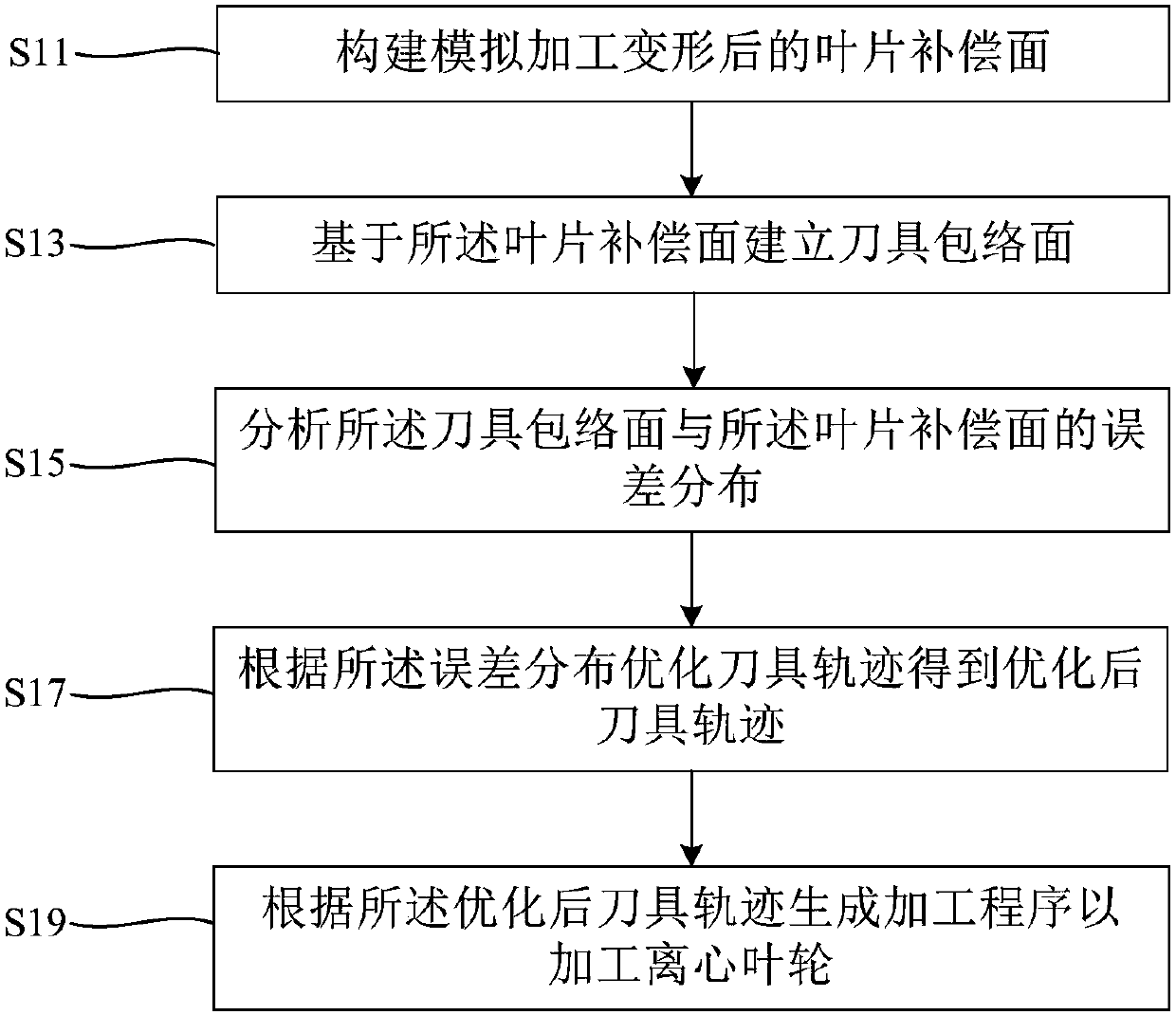
[0036] see figure 1 , which is a schematic flowchart of a centrifugal impeller cutting method provided by the first embodiment of the present invention. The centrifugal impeller cutting processing method provided by the embodiment of the present invention is suitable for a multi-axis machine tool, such as a five-axis linkage CNC machining machine tool, for a centrifugal impeller, such as an integral centrifugal impeller. like figure 1 As shown, the centrifugal impeller cutting processing method provided by the embodiment of the present invention includes the steps:
[0037] S11: Construct the blade compensation surface after simulated machining deformation;
[0038] S13: Establish a tool envelope surface based on the blade compensation surface;
[0039] S15: Analyze the error distribution between the tool envelope surface and the blade compensation surface;
[0040] S17: Optimizing the tool path according to the error distribution to obtain an optimized tool path; and
[...
no. 2 example
[0052] In addition, the second embodiment of the present invention provides a centrifugal impeller cutting method, including:
[0053] First, create the blade compensation surface. The three-dimensional model of the centrifugal impeller is established, and the three-dimensional model of the overall centrifugal impeller is simulated, analyzed and processed, and finally the blade compensation surface after the elastic deformation of the centrifugal impeller is constructed. Specifically, the three-dimensional model of the centrifugal impeller is established in the three-dimensional modeling software, and the three-dimensional model of the centrifugal impeller is imported into the analysis software for static analysis and milling process simulation. Perform related settings and definitions in the analysis software, for example, define material properties, specify element types, mesh division, constraint definition, define several tool position points for u-direction parameters and...
no. 3 example
[0100] like Figure 14 As shown, the third embodiment of the present invention provides a centrifugal impeller cutting processing device 10 . Centrifugal impeller cutting processing device 10 includes:
[0101] The blade compensation surface construction module 110 is used to construct the blade compensation surface after simulating machining deformation;
[0102] A cutter envelope surface establishing module 120, configured to establish a cutter envelope surface based on the blade compensation surface;
[0103] The error distribution analysis module 130 is used to analyze the error distribution of the tool envelope surface and the blade compensation surface;
[0104] The tool trajectory optimization module 140 is used to obtain the optimized tool trajectory according to the error distribution and the tool position optimization algorithm; and
[0105] The numerical control program generation module 150 is used to generate a numerical control program according to the optimiz...
PUM
 Abstract
Description
Claims
Application Information
 - R&D Engineer
- R&D Manager
- IP Professional
- Industry Leading Data Capabilities
- Powerful AI technology
- Patent DNA Extraction
Browse by: Latest US Patents, China's latest patents, Technical Efficacy Thesaurus, Application Domain, Technology Topic.
© 2024 PatSnap. All rights reserved.Legal|Privacy policy|Modern Slavery Act Transparency Statement|Sitemap