Plastering machine automatic horizontal moving and walking control method and plastering robot

A technology of walking control and plastering machine, which is applied in the direction of construction and building structure, and can solve the problems of uneven plastering thickness, uneven wall surface, and complicated operation.

Active Publication Date: 2019-04-05
深圳市森博机器人有限公司
View PDF7 Cites 5 Cited by
  • Summary
  • Abstract
  • Description
  • Claims
  • Application Information

AI Technical Summary

Problems solved by technology

[0003] Taking the plastering machine as an example, in the process of using the plastering machine to construct the entire wall, it is often necessary to adjust the position of the plastering machine in translation from left to right; since the bottom of the plastering machine is generally equipped with casters, the At present, the usual method used in the industry is: when one of the walls is completed, the on-site construction personnel will push the overall position of the plastering machine to adjust the position, in order to keep the plastering machine (especially the plastering machine head) in line with the wall. In the parallel state, it is moved t

Method used


Image

  • Plastering machine automatic horizontal moving and walking control method and plastering robot
  • Plastering machine automatic horizontal moving and walking control method and plastering robot
  • Plastering machine automatic horizontal moving and walking control method and plastering robot

Examples


Embodiment Construction

[0033] The embodiments of the present invention will be described in detail below with reference to the accompanying drawings, but the present invention can be implemented in many different ways defined and covered by the claims.

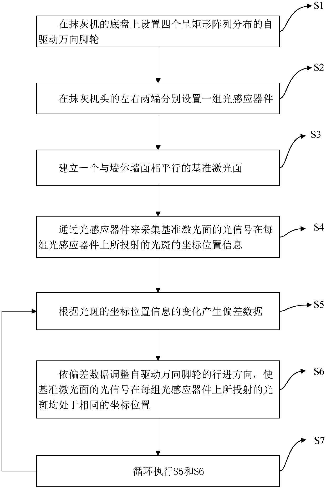
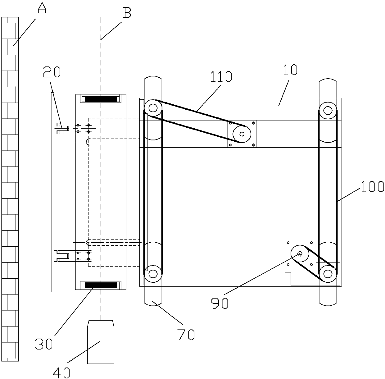
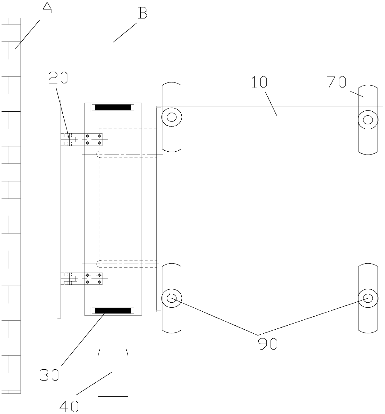
[0034] like Figure 1 to Figure 4 As shown, the present embodiment provides a plastering machine automatic translation walking control method, which includes the following steps:

[0035] S1. Set four self-driven universal casters in a rectangular array on the chassis 10 of the plastering machine to ensure that the connecting line between the center points of two adjacent self-driven universal casters is at the plastering distance with the plastering machine The front end face of the machine head 20 is parallel or in a plane perpendicular to it; the self-driven universal caster mentioned above means that the caster can move in a horizontal plane (that is, a plane parallel to the chassis 10 or the ground) under the action of the power control compone...


PUM


Abstract

The invention discloses a plastering machine automatic horizontal moving and walking control method and a plastering robot. The method comprises the steps that S1, four self-driven universal trundlesdistributed in a rectangular array are arranged on a chassis of a plastering machine; S2, the left end and the right end of a plastering machine head are both provided with a group of light sensing devices; S3, a reference laser surface parallel to the wall surface of a wall body is established; S4, coordinate position information of light spots projected by light signals of the reference laser surface on each group of the light sensing devices is collected through the light sensing devices; S5, deviation data is generated according to the change of the coordinate position information of the light spot; S6, the advancing direction of the self-driven universal trundles is adjusted according to the deviation data, so that the light spots projected by the light signals of the reference lasersurface on each group of the light sensing devices are located at the same coordinate positions. The effect of dynamically correcting the advancing path of the plastering machine can be achieved, it is guaranteed that the plastering machine is always parallel to the wall surface of the wall body in the process that the plastering machine moves left and right, and the construction operation efficiency can be greatly improved.

Description

technical field [0001] The invention relates to the technical field of building construction, in particular to a control method for automatic translational movement of a plastering machine and a plastering robot with automatic translational movement function based on the method. Background technique [0002] The slurry (such as mortar or mortar, etc.) smearing and covering process on the surface of buildings is an important construction project in the construction field, mainly through the surface of buildings such as walls, canopies, roofs, balconies, etc. The slurry is applied to achieve the purpose of improving the indoor environment of the building or improving the architectural performance of the building such as heat insulation, moisture resistance and weather resistance. The traditional slurry smearing and covering process is mainly to smear the slurry on the surface of the blank wall by manually holding a special tool. The workload is large, the work efficiency is lo...

Claims


Application Information

Patent Timeline
IPC IPC(8): E04F21/08E04F21/04
CPCE04F21/04E04F21/08
Inventor 孙镇何昌秋杜加才
Owner 深圳市森博机器人有限公司
Why Eureka
Try Eureka