
Main oscillation power amplifier structure-based pulse fiber laser

A technology for power amplifiers and fiber lasers, applied in the direction of lasers, laser components, and the structure/shape of active media, can solve the problems of pulse power loss, lack of mature and stable commercial devices, etc., and achieve easy adjustment and insensitive wavelength stability , the effect of small insertion loss

Pending Publication Date: 2019-04-05
武汉孚晟科技有限公司
View PDF0 Cites 2 Cited by
  • Summary
  • Abstract
  • Description
  • Claims
  • Application Information

AI Technical Summary

Problems solved by technology

At present, in fiber lasers, these kinds of saturable absorbers are mainly used to achieve mode-locking and Q-switching of lasers, but due to their high saturated absorption power, if they are used to suppress ASE in optical amplifiers, the loss of pulse power is relatively small. Large, and except for semiconductor saturable absorption mirrors, there are no mature and stable commercial devices for the other materials

Method used


Image

  • Main oscillation power amplifier structure-based pulse fiber laser
  • Main oscillation power amplifier structure-based pulse fiber laser

Examples


Embodiment 1

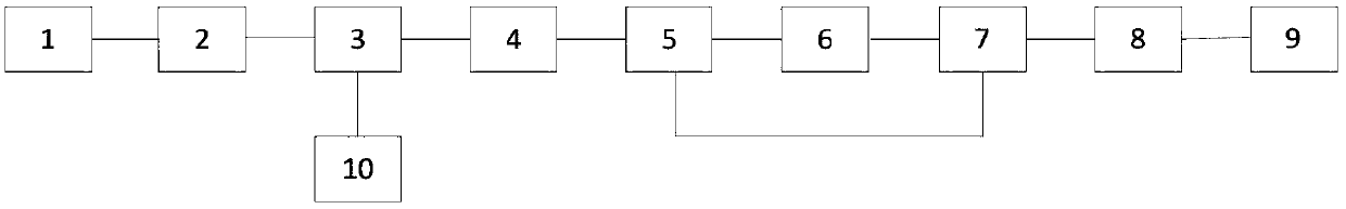
[0020] Such as figure 1 As shown, this embodiment provides a pulsed fiber laser based on a main oscillator power amplifier structure, including a pulsed seed light source 1, a first isolator 2, a first wavelength division multiplexer 3, and a first doped fiber 4 , a second wavelength division multiplexer 5, a second doped fiber 6, a third wavelength division multiplexer 7, a third doped fiber 8, a second isolator 9 and a single-mode pump laser 10;

[0021]Specifically, the output end of the pulsed seed light source 1 is connected to the input end of the first isolator 2, and the output end of the first isolator 2 is connected to the signal end of the first wavelength division multiplexer 3, and the first wave The pump end of the division multiplexer 3 is connected to the output end of the single-mode pump laser 10, and the common end of the first wavelength division multiplexer 3 is connected to the input end of the first doped fiber 4, and the first doped fiber The output en...

Embodiment 2

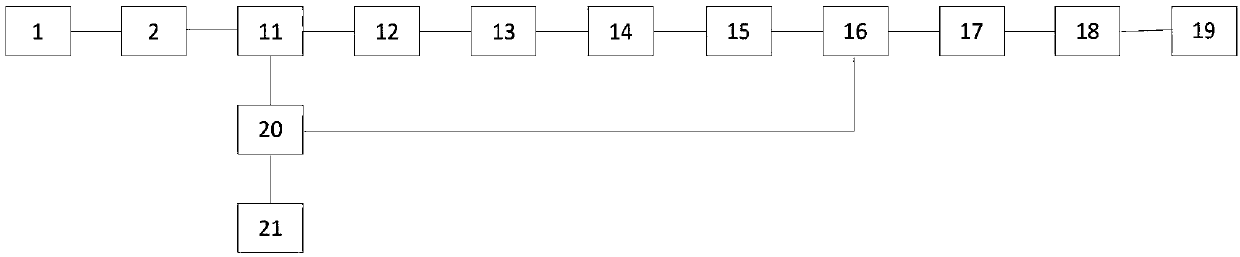
[0030] Such as figure 2 As shown, this embodiment provides a pulsed fiber laser based on a main oscillator power amplifier structure, and the main difference from the above-mentioned embodiment 1 is that the pump laser in this embodiment is a multi-mode pump laser 21;

[0031] Specifically, the pulsed fiber laser of this embodiment includes a pulsed seed light source 1, a first isolator 2, a first multimode pump combiner 11, a fourth doped fiber 12, a first pump stripper 13, a first Multimode isolator 14, fifth doped fiber 15, second multimode pump combiner 16, sixth doped fiber 17, second pump stripper 18, second multimode isolator 19, multimode pump A pump splitter 20 and a multimode pump laser 21;

[0032] Specifically, the output end of the pulsed seed light source 1 is connected to the input end of the first isolator 2, and the output end of the first isolator 2 is connected to the signal end of the first multimode pump combiner 11, and the first The pump end of the mu...


PUM


Abstract

The invention discloses a main oscillation power amplifier structure-based pulse fiber laser. The main oscillation power amplifier structure-based pulse fiber laser comprises a pulse seed light source, an input isolator, a wavelength division multiplier, a pumping laser, a plurality of doping fibers and an output isolator, wherein the plurality of doping fibers comprises doping fibers used for amplifying pulse seed light and doping fibers used as a saturation absorption body to absorb ASE noise, the pulse seed light source, the input isolator, the wavelength division multiplier, the doping fibers and the output isolator are sequentially connected, and the wavelength division multiplier is connected with the pumping laser. The doping fibers with very short length are introduced into the doping fibers of an optical amplifier and are used as the saturation absorption body, so that the influence of the improvement of ASE power on the laser gain at a gap of two pulses can be reduced, and the output pulse optical peak power and the signal-to-noise ratio are improved.

Description

technical field [0001] The invention belongs to the technical field of fiber lasers, in particular to a pulsed fiber laser based on a main oscillation power amplifier structure that can effectively increase pulse output power, reduce laser output amplification spontaneous emission noise (ASE noise), and improve pump conversion efficiency. Background technique [0002] High-power pulsed fiber lasers are widely used in laser processing, material processing, lidar and remote sensing. Acousto-optic Q-switched fiber lasers generate laser pulses through Q-switching technology, but the adjustment range of parameters such as output pulse width and repetition frequency is limited; while fiber lasers based on the main oscillator power amplifier (MOPA) structure are generated by semiconductor lasers as seed light sources Pulse signal light, and then power amplify the seed light in the fiber amplifier. Since the semiconductor laser seed source can be directly electrically modulated, it...

Claims


Application Information

Patent Timeline
Patent Type & Authority Applications(China)
IPC IPC(8): H01S3/067H01S3/11
CPCH01S3/06708H01S3/06758H01S3/11
Inventor 马延峰
Owner 武汉孚晟科技有限公司
Features
  • Generate Ideas
  • Intellectual Property
  • Life Sciences
  • Materials
  • Tech Scout
  • Unparalleled Data Quality
  • Higher Quality Content
  • 60% Fewer Hallucinations
Learn More