Method and device for drying materials

A technology of drying device and drying method, which is applied in the direction of drying gas arrangement, heating device, drying solid materials, etc., can solve the problems of friction and corrosion of rotary heating pipe, difficult adjustment and control of feeding and discharging materials, and excessive drying of fine particles.

Inactive Publication Date: 2019-04-09
TIANJIN UNIV
View PDF13 Cites 3 Cited by
  • Summary
  • Abstract
  • Description
  • Claims
  • Application Information

AI Technical Summary

Problems solved by technology

However, for materials with a large amount of fine powder and a wide particle distribution, airflow drying is likely to cause insufficient drying of large particles and excessive drying of fine particles due to the short gas-solid contact time; In the strong case, the rotary tube drying is easy to cause the friction and corrosion of the rotary heating tube du

Method used


Image

  • Method and device for drying materials
  • Method and device for drying materials
  • Method and device for drying materials

Examples


Embodiment 1

[0049] This example is an implementation of a coking coal drying method and device using an oscillating moving bed dryer.

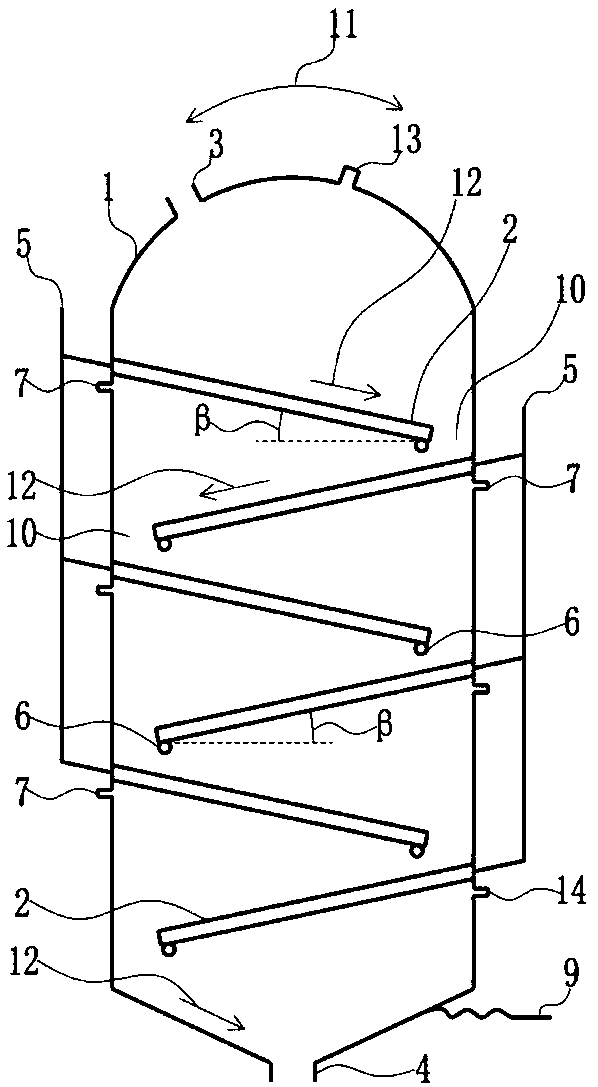
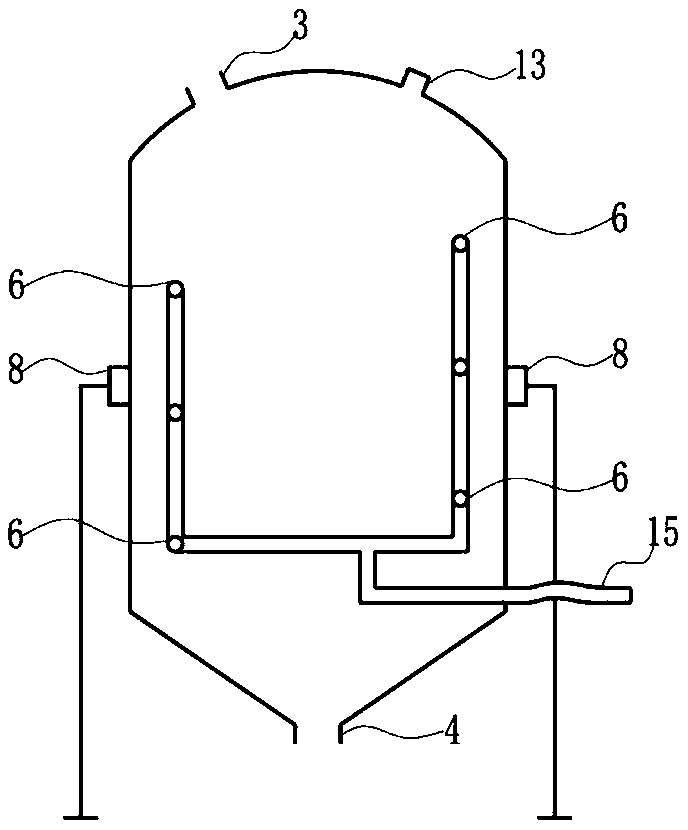
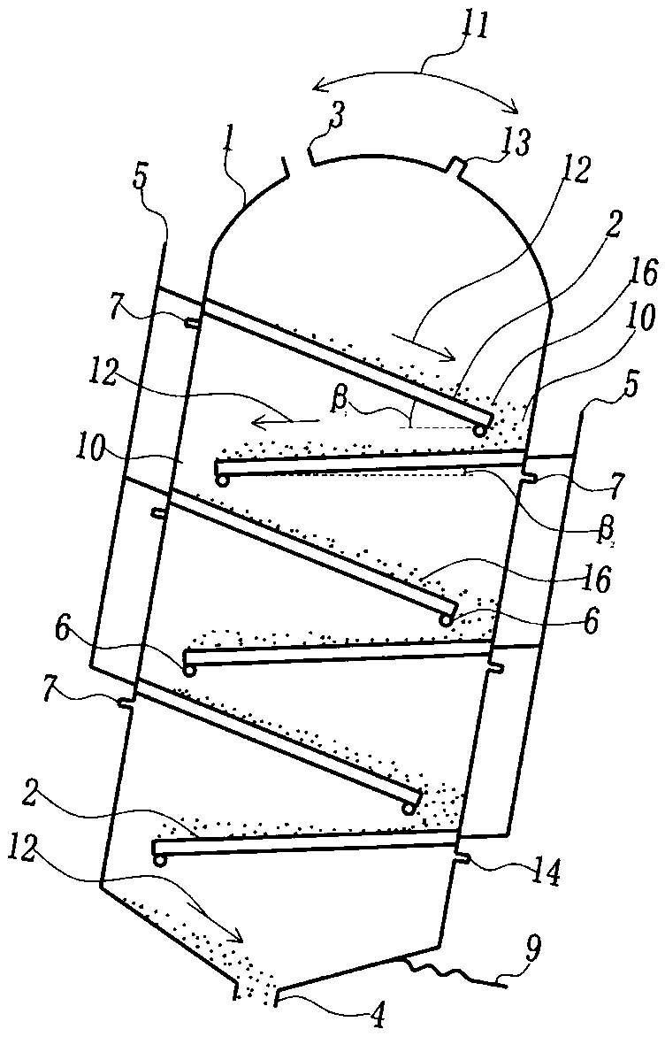
[0050] Dryer such as figure 1 and figure 2 As shown, the shell of the dryer 1, the inclined heating plate 2, the material inlet 3, the material outlet 4, the heat source inlet 5, the heat source outlet 6, the evaporation steam outlet 7 of the steam generated by the evaporation of water in the material, the dryer support mechanism 8 and the drying In the dryer composed of the swing mechanism 9, inclined heating plates 2 inclined in opposite directions are arranged alternately from top to bottom, the high side of the inclined heating plate is connected with the shell of the dryer, and the material Downflow drop opening 10. The dryer is driven by the swing mechanism 9 to swing in the swing direction 11 . The material is sent in from the material inlet 3 set on the top of the dryer. When the dryer is swinging to the right (such as image 3 As shown), the...

Embodiment 2

[0054] The present embodiment is basically the same as Embodiment 1, except that the dry material is lignite, which is dried to 15% by moisture content of 30%. The heat source used is heat conduction oil, the heat source inlet is 200°C, and the heat source outlet is 150°C. The swing mechanism of the dryer is driven by a hydraulic cylinder. When the vertical axis of the dryer is in a vertical state, the angle between the inclined heating plate and the horizontal plane, that is, the inclination angle of the heating plate is 25°. The supporting structure of the dryer used is a cylindrical bearing arranged in the middle of the dryer, and the swing mechanism is a chain driven by a motor arranged in the lower part. Due to the high moisture content of the fed material and the large frictional sliding angle, in order to avoid too large a swing range, a structure with a large inclination angle β of the heating plate is adopted. At the same time, due to the large moisture difference o...

Embodiment 3

[0057] The present embodiment is basically the same as embodiment 1, except that the drying object is flour, which is dried to 8% by moisture 13%. The supporting structure of the dryer used is a cylindrical bearing arranged in the middle of the dryer, and the swing mechanism is a gear driven by a motor arranged in the lower part. When the vertical axis of the dryer is in a vertical state, the angle between the inclined heating plate and the horizontal plane, that is, the inclination angle of the heating plate is 10°.

[0058] The smooth drying of flour is realized, and the flour carry-out is little, which reduces the recovery load caused by the flour carry-out.


PUM


Abstract

The invention relates to a method and device for drying materials. A moving bed drier consisting of heating plates which are alternately sloped in the opposite direction is driven by a swinging mechanism to swing, and the sloping angles of the sloped heating plates are extended, so that the materials are promoted to flow, moving of the materials on the heating plates and material transporting between the heating plates from top to bottom are realized, and high-efficient drying of the materials in the moving bed drier and smooth material moving are achieved; through the adjustment of swinging range and swinging speed, the adjustment of drying capacity is realized, and ordered controllable moving of the materials from top to bottom is simply realized; the control of thickness of feeding layers of the heating plates of the materials and interface updating of materials in layers and heating surfaces are also realized, and smooth moving and smooth discharging of the materials are realized.The method disclosed by the invention has the characteristics of being low in investment cost, low in operation power consumption, low in equipment wear, low in dust removal load, and simple and efficient in device, and a high-efficient low-cost technique and device guarantee are provided for drying of the materials.

Description

technical field [0001] The invention relates to a material drying method and device, in particular to a method and device for drying coal, mineral powder, grain, chemical raw materials and other materials to reduce moisture, and belongs to the field of drying and environmental protection. Background technique [0002] In industrial production, there are many unit processes that need to reduce the moisture content of materials, such as drying coal, mineral powder, grain, chemical raw materials and other materials to reduce moisture content. In the drying of these materials, there are many methods widely used in production, such as air flow drying, rotary tube drying, moving bed drying and so on. However, for materials with a large amount of fine powder and a wide particle distribution, airflow drying is likely to cause insufficient drying of large particles and excessive drying of fine particles due to the short gas-solid contact time; In the strong case, the rotary tube dry...

Claims


Application Information

Patent Timeline
IPC IPC(8): F26B17/12F26B23/00F26B21/14F26B25/00
CPCF26B17/12F26B21/14F26B23/00F26B25/00
Inventor 张书廷马丽
Owner TIANJIN UNIV
Why Eureka
Try Eureka