
Axial distributed three-dimensional imaging method based on double wedged prisms

A three-dimensional imaging, double-wedge technology, applied in the field of integrated imaging, can solve the problems such as the inability to meet the requirements of real-time dynamic display of integrated imaging of spatial scenes, the difficulty of camera spatial position and optical axis direction, and the limitation of the application of integrated imaging technology, and achieve effective three-dimensional images. Reconstruction, smear avoidance, simple structure effect

Inactive Publication Date: 2019-04-09
TONGJI UNIV
View PDF5 Cites 7 Cited by
  • Summary
  • Abstract
  • Description
  • Claims
  • Application Information

AI Technical Summary

Problems solved by technology

[0004] Both of these technologies use the movement of the camera to record the image, but the image recording area of ​​these methods is limited, and the recorded image only contains horizontal (or vertical) perspective information, plus the spatial position of the camera and the direction of the optical axis are moving. It is difficult to accurately control the process, and the number of cameras used in the camera array is too large, so it cannot meet the requirements of real-time dynamic display of integrated imaging of space scenes, which greatly limits the application of integrated imaging technology

Method used


Image

  • Axial distributed three-dimensional imaging method based on double wedged prisms
  • Axial distributed three-dimensional imaging method based on double wedged prisms
  • Axial distributed three-dimensional imaging method based on double wedged prisms

Examples


Embodiment

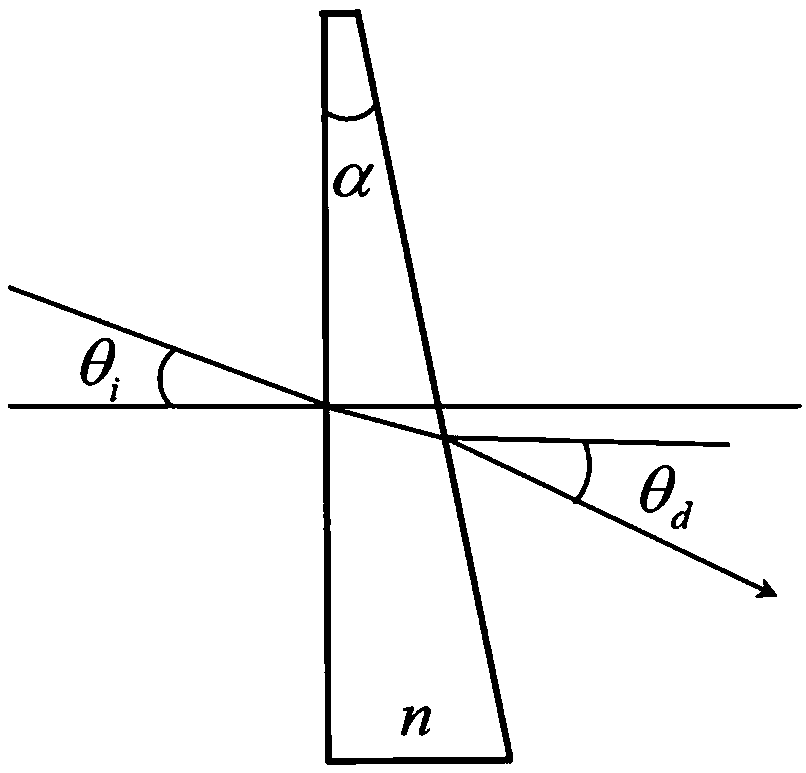
[0034] The double wedge prism system is composed of two wedge prisms. The angle between the "plane" and "wedge plane" of the prism is called the wedge angle. According to the principle of refraction, the wedge prism can realize the deflection of the beam direction. In this embodiment, the wedge prism The position of the main section to represent the position of the prism, such as figure 1 shown. When the ray and the optical axis form θ i Angle incident on the vertical surface of the prism, the angle between the exit light of the wedge surface and the optical axis is θ d , for small wedge angle α and incident angle θ i In the smaller case, we can get by the refraction theorem

[0035] θ d ≈(n-1)α+θ i (1)

[0036] where n is the refractive index of the prism material.

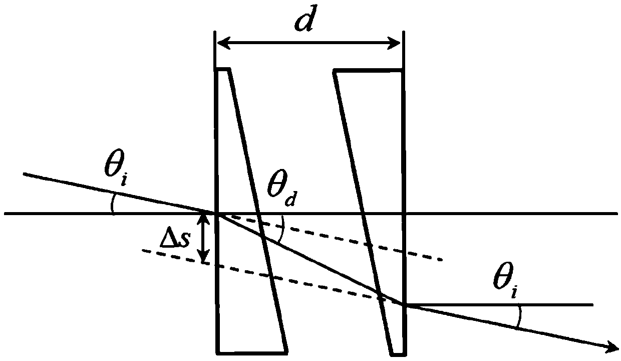
[0037] For the double wedge prism system, the two prisms are arranged symmetrically to the center, that is, the plane of the first prism, the wedge plane of the first prism, the wedge plane of the second ...


PUM


Abstract

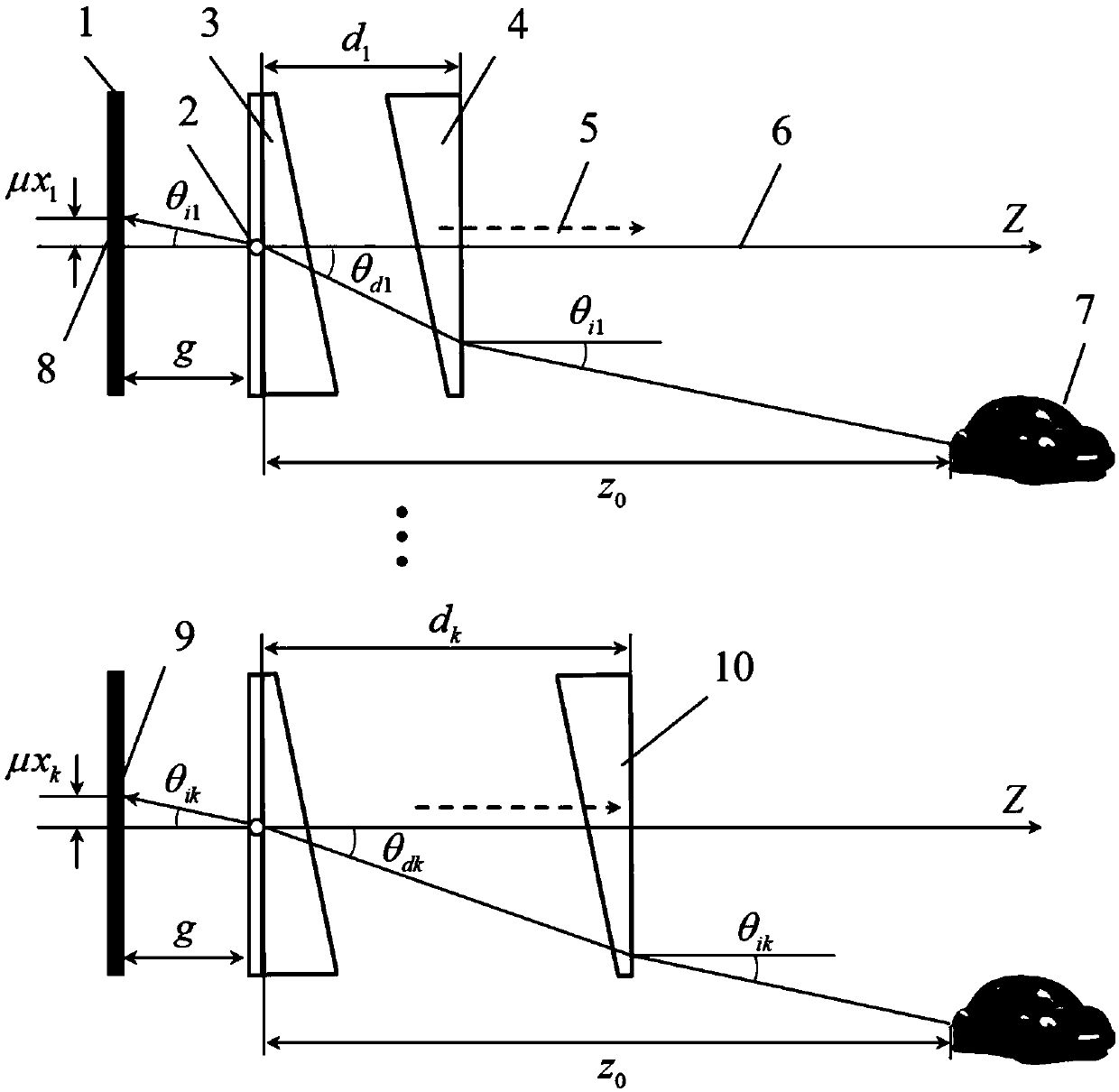
The invention relates to an axial distributed three-dimensional imaging method based on double wedged prisms. The method includes two processes of acquisition of multi-visual-angle element images andreconstruction of a three-dimensional image. The acquisition process of the multi-visual-angle element images includes steps: maintaining a camera and a first prism still by employing the refraction effect of a light beam by the double wedged prisms, and intermittently acquiring the multi-visual-angle element images, regarded as 3D scenes, of a traverse perspective and a vertical perspective of atarget object through one-dimensional movement of a second prism along an optical axis. The reconstruction process of the three-dimensional image includes steps: performing back projection of the recorded element images to a virtual space scene through a virtual pinhole according to a back projection algorithm, superposing the amplified and shifted element images on the same reconstruction plane,and selecting a pixel average value of a new overlapping region to form a constructed image of the three-dimensional image. Compared with the prior art, according to the method, an approach for real-time dynamic display of space scene integrated imaging is provided, and the application of the integrated imaging technology enriched.

Description

technical field [0001] The invention relates to integrated imaging technology, in particular to an axially distributed three-dimensional imaging method based on double wedge prisms. Background technique [0002] Integrated imaging technology is a 3D image technology that uses a microlens array to record and reproduce a space scene. It includes two processes of recording and reproduction: the recording process uses a recording microlens array to obtain the three-dimensional information of the object space scene; The reproduction process uses the reversible principle of the reproduction microlens array to reconstruct the three-dimensional scene in the viewing space. [0003] In order to obtain high-resolution recorded images, a synthetic aperture was proposed in the prior art (Jang J S, Javidi B.Three-dimensional synthetic aperture integral imaging[J].Optics Letters,2002,27(13):1144-6.) Type-integrated imaging (SAII) technology, through the movement of the sub-integrated imag...

Claims


Application Information

Patent Timeline
IPC IPC(8): G03B35/02H04N13/218G06T17/00G06T11/00
CPCG03B35/02G06T11/006G06T17/00G06T2200/08
Inventor 李安虎龚炜
Owner TONGJI UNIV
Learn More