Optical module and signal processing method

A technology of optical modules and electrical signals, which is applied in the field of communication, can solve problems such as difficulty in meeting the application requirements of PON systems with multiple different rates, and achieve the effect of reducing construction and maintenance costs and improving service quality

Active Publication Date: 2019-04-09
ZTE CORP
View PDF6 Cites 8 Cited by
  • Summary
  • Abstract
  • Description
  • Claims
  • Application Information

AI Technical Summary

Problems solved by technology

[0007] The embodiment of the present invention provides an optical module and a signal processing method to at least solve the problem that the optical module in the related art cannot meet the application requirements of multiple PON systems with different rates The problem

Method used


Image

  • Optical module and signal processing method
  • Optical module and signal processing method
  • Optical module and signal processing method

Examples


specific Embodiment 1

[0075] The optical module in this embodiment is as Figure 6 As shown, the optical module includes a modulation format selection module, an optical transmitting assembly (TOSA), and an optical receiving assembly (ROSA).

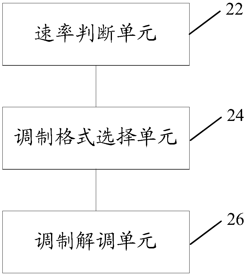
[0076] The above-mentioned modulation format selection module mainly consists of a rate judging unit (that is, the above-mentioned rate judging unit 12, which can be arranged in the modulation format selection module, and can also exist independently of the modulation format selection module), modulation format selection Unit (corresponding to the above-mentioned modulation format selection unit 14), modulation format unit (NRZ / PAM2, PAM4, PAM8...) and other components to realize the judgment and identification of the input electrical signal rate, modulation format selection, modulation format generation / demodulation function.

[0077] Take the input of a 50Gb / s NRZ signal, using TOSA and ROSA with a supported symbol rate of 25Gbaud / s as an example (actually...

specific Embodiment 2

[0086] The schematic diagram of the composition of the rate-adaptive optical module provided by the specific embodiment 2 is as follows Figure 9 shown. It is mainly composed of a modulation format selection module, an optical transmitting assembly (TOSA), and an optical receiving assembly (ROSA). The modulation format selection module is also mainly composed of a rate judgment unit, a modulation format selection unit, and a modulation format unit (NRZ / PAM2, PAM4, PAM8...), etc., to realize the judgment and identification of the input electrical signal rate, the selection of the modulation format, and the generation of the modulation format / demodulation function. The difference from the first embodiment is that the electrical interface between the equipment side and the optical module is not one, but 2, 3, 4, or even N. At this time, a control unit needs to be added to the rate judgment and selection unit, and the rate judgment unit is configured with information such as how...

specific Embodiment 3

[0088] The schematic diagram of the composition of the rate adaptive optical module provided by the specific embodiment three is as follows Figure 10 shown. It is mainly composed of modulation format selection module, TOSA and ROSA. The modulation format selection module is also mainly composed of a rate judgment unit, a modulation format selection unit, and a modulation format unit (NRZ / PAM2, PAM4, PAM8...), etc., to realize the judgment and identification of the input electrical signal rate, the selection of the modulation format, and the generation of the modulation format / demodulation function. It is also aimed at the situation that the electrical interface between the equipment side and the optical module is not only one line of data, but 2 lines, 3 lines, 4 lines, or even N lines. At this time, a control unit needs to be added to the rate judgment and selection unit, and the rate judgment unit is configured with information such as how many signals on the electrical...


PUM


Abstract

The invention provides an optical module and a signal processing method. The method comprises the steps: determining the total rate of electric signals inputted into or outputted from the optical module; determining a modulation format corresponding to the total rate of the electric signal inputted into the optical module according to the total rate of the electric signal inputted into the opticalmodule and a preset corresponding relation between the total rate of the electric signal and the modulation format; or determining a demodulation format corresponding to the total rate of the electric signal of the output optical module according to the total rate of the electric signal of the output optical module and a preset corresponding relation between the total rate of the electric signaland the demodulation format; modulating an electric signal input into the optical module by using the determined modulation format; or demodulating the electric signal subjected to photoelectric conversion by using the determined demodulation format. The problem that an optical module in the prior art cannot easily meet the application requirements of PON systems with different rates is solved, and the effects of reducing the construction and maintenance cost of the system and improving the service quality assurance of the system are achieved.

Description

technical field [0001] The present invention relates to the communication field, in particular to an optical module and a signal processing method. Background technique [0002] With the rapid development of services such as communications and the Internet, the demand for bandwidth for large-traffic services such as Internet TV, high-definition TV, and video continues to increase and accelerate. As the last mile of the entire communication network, the access network is gradually developing from simple voice requirements to data, multimedia, and integrated service requirements. These integrated service applications have higher and higher bandwidth requirements. As a solution among service providers, telecommunication central offices and business / home users, Passive Optical Network (PON for short) emerges as the times require. PON is a single-fiber bidirectional optical access network based on point-to-multipoint topology. The PON system is mainly composed of an Optical Lin...

Claims


Application Information

Patent Timeline
Patent Type & Authority Applications(China)
IPC IPC(8): H04B10/40H04B10/516H04L1/00H04L27/00
CPCH04B10/40H04B10/5161H04L1/0003H04L27/0008H04B10/272H04B10/516H04L1/00H04L27/00
Inventor 涂芝娟杨波黄新刚张俊文
Owner ZTE CORP
Why Eureka
Try Eureka