Rotary continuous capacitive deionizing desalting device

A technology of capacitive deionization and desalination device, applied in the field of desalination, can solve problems such as discontinuous production, and achieve the effects of low energy consumption, improved conversion rate, and improved desalination efficiency

Pending Publication Date: 2019-04-12
TIANJIN UNIV
View PDF6 Cites 10 Cited by
  • Summary
  • Abstract
  • Description
  • Claims
  • Application Information

AI Technical Summary

Problems solved by technology

[0005] The purpose of the present invention is to solve the production discontinuity caused by periodic charging and discharging of electrodes in the traditional capacitive deionization and desalination process, and to provide a rotary continuous capacitive deionization and desalination device

Method used


Image

  • Rotary continuous capacitive deionizing desalting device
  • Rotary continuous capacitive deionizing desalting device
  • Rotary continuous capacitive deionizing desalting device

Examples


Embodiment 1

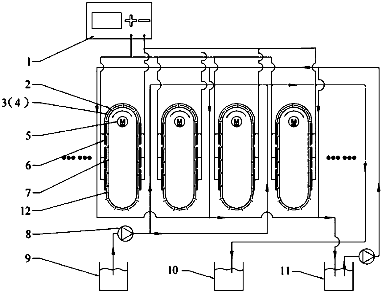
[0034] In Embodiment 1 of the present invention, the width of the conveyor belt 12 is 2 cm, the length of the straight section can be 10 cm, the radius of the bent section can be 10 cm, and the inside of the conveyor belt 12 is supported by a frame with a fixed shape. Multiple groups of conveyor belts 12 are placed side by side.

[0035] In Embodiment 1 of the present invention, the two adjacent groups of conveyor belts 12 rotate in opposite directions.

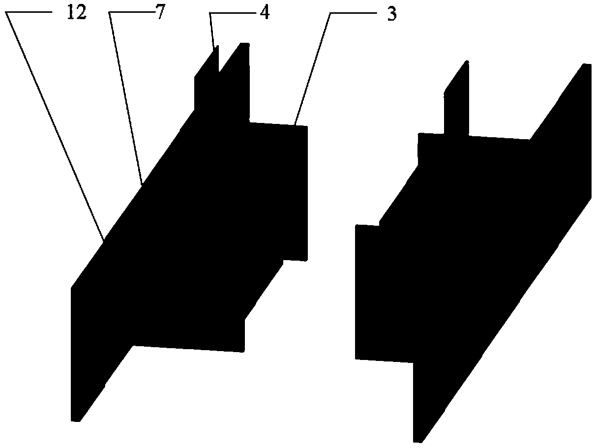
[0036] In Embodiment 1 of the present invention, the electrode 3 may have a thickness of 2 mm, a length consistent with the width of the conveyor belt 12, and a width of 0.5 mm. Its placement direction is that the length direction is consistent with the width direction of the conveyor belt 12 .

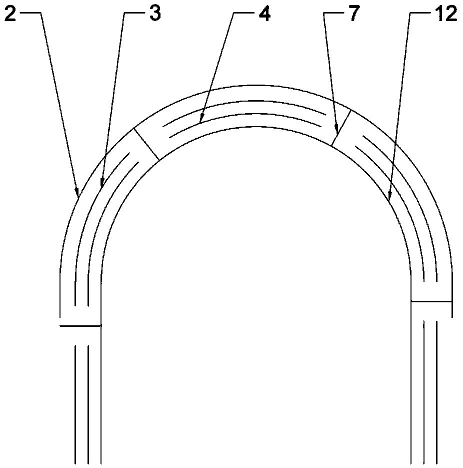
[0037] In Embodiment 1 of the present invention, the width of the semicircular baffle 2 is consistent with the width of the conveyor belt 12, and the radius of the semicircular baffle 2 is the radius of the bent section of the conve...

Embodiment 2

[0042] In Embodiment 2 of the present invention, the width of the conveyor belt 12 can be 7cm, the length of the straight section can be 100cm, and the radius of the bent section can be 30cm, and the interior of the conveyor belt 12 is supported by a fixed-shaped frame. Multiple groups of conveyor belts 12 are placed side by side.

[0043] In Embodiment 2 of the present invention, the two adjacent groups of conveyor belts 12 rotate in opposite directions.

[0044] In Embodiment 2 of the present invention, the electrode 3 may have a thickness of 4mm, a length consistent with the width of the conveyor belt 12, and a width of 6cm. Its placement direction is that the length direction is consistent with the width direction of the conveyor belt 12 .

[0045] In Embodiment 2 of the present invention, the width of the semicircular baffle 2 is consistent with the width of the conveyor belt 12, and the radius of the semicircular baffle 2 is the radius of the curved edge of the conveyor...

Embodiment 3

[0050] In Embodiment 3 of the present invention, the width of the conveyor belt 12 can be 5cm, the length of the straight section can be 300cm, the radius of the bent section can be 20cm, and the interior of the conveyor 2 is supported by a fixed shape frame. Multiple groups of conveyor belts 12 are placed side by side.

[0051] In Embodiment 3 of the present invention, the two adjacent groups of conveyor belts 12 rotate in opposite directions.

[0052] In Embodiment 3 of the present invention, the electrode 3 may have a thickness of 3mm, a length consistent with the width of the conveyor belt 12, and a width of 2cm. Its placement direction is that the length direction is consistent with the width direction of the conveyor belt 12 .

[0053] In Embodiment 3 of the present invention, the width of the semicircular baffle 2 is consistent with the width of the conveyor belt 12, and the radius of the semicircular baffle 2 is the radius of the curved edge of the conveyor belt 12 + ...


PUM

PropertyMeasurementUnit
widthaaaaaaaaaa
lengthaaaaaaaaaa
radiusaaaaaaaaaa

Abstract

The invention discloses a rotary continuous capacitive deionizing desalting device. The device comprises a transmission system, a water feeding system, a capacitive deionizing system and an energy supply system; electrodes are driven to be switched among desalting areas, a sealing area, regenerating areas and dehydration areas through a conveyor belt; an adsorbing flow path is arranged between thetwo desalting areas, and ions in brackish water passing through the adsorbing flow path are adsorbed to the surfaces of the electrodes to achieve the desalting effect on the brackish water; a desorbing flow path is arranged between the two regenerating areas, the ions adsorbed by the electrodes are released in concentrated saline water again, and the purpose of regenerating the electrodes is achieved; through switching of the electrodes, the continuous desalting effect on the brackish water is achieved. According to the rotary continuous capacitive deionizing desalting device, by changing theworking structure of the capacitive deionizing desalting device, the purposes that the adsorbing flow path of the capacitive deionizing desalting device continuously desalts water, and continuous andstable purified water is obtained at an outlet end of the adsorbing flow path are achieved, and the desalting efficiency for capacitive deionizing is effectively improved.

Description

technical field [0001] The invention relates to desalination technology, in particular to a continuous capacitive deionization desalination device based on a rotating conveyor belt, which can be applied to the purification of waste water containing inorganic salts, the softening of hard water containing calcium and magnesium ions, and the drinking water containing heavy metal ions Purification, low-salinity surface water purification. Background technique [0002] Fresh water resources are a necessity for human life, and the shortage of its storage has become an urgent problem to be solved. If seawater or brackish water can be converted into pure water, it will effectively solve the problem of shortage of fresh water resources. [0003] The desalination technologies widely used in the world include distillation, electrodialysis, ion exchange and reverse osmosis. With the development of technology, reverse osmosis method (64%), multi-stage flash evaporation method (23%) and...

Claims


Application Information

Patent Timeline
Patent Type & Authority Applications(China)
IPC IPC(8): C02F1/469
CPCC02F1/4691
Inventor 汪洋赵聪刘丽艳
Owner TIANJIN UNIV
Why Eureka
Try Eureka