Mechanical transmission-free jet flow spray-adjustable cooling method and device

A cooling device, spray cooling technology, applied in the direction of mechanical equipment, heating methods, air conditioning systems, etc., can solve problems such as the overwhelmed maintenance costs of ventilation components, failure of operation balance, wear and tear of rotating bearing components, etc., to eliminate backflow sinking pressure Effects of wind damage, removal of performance limitations, and enhancement of cooling performance

Pending Publication Date: 2019-04-12
重庆浪格节能环保科技有限公司
View PDF6 Cites 2 Cited by
  • Summary
  • Abstract
  • Description
  • Claims
  • Application Information

AI Technical Summary

Problems solved by technology

There are several major problems in the above technology: ①Continuous energy consumption, because the fan is driven by the motor; ②Regular maintenance is required, and replacement is due, because there are mechanical fan transmission and deceleration components in the core structure; ③Reliability continues to decline, due to mechanical transmission bearing components, etc. The service life is limited. With long-term continuous operation, the core mechanical fan deceleration transmission system will have reliability problems such as increased vibration and failure of operation balance; ④Regular maintenance and replacement are required, and the cooling effect will gradually decrease. Continuous operation, algae growth, dust accumulation, etc., will gradually block the gaps in the packing, resulting in a decrease in cooling efficiency, so regular cleaning, maintenance and replacement are required
There are several major problems with this technology: ①Continuous energy consumption, because the fan is driven by the motor; ②Regular maintenance is required and replaced when due, because there are mechanical transmission deceleration parts in the core structure; ③Reliability continues to decline, due to mechanical transmission bearing components, etc. The service life is limited. With long-term continuous operation, the core mechanical fan deceleration transmission system will have reliability problems such as increased vibration and failure of operation balance; ④The large flow resistance and poor cooling performance, because the nozzle components are concentrated vertically upward spray, the spray flow is concentrated In the center of the tower, the ventilation resistance at the bottom of the tower is very large, and the intake of cold air is greatly reduced, which eventually leads to poor cooling performance of the whole tower; And water pressure and other actual needs, not conducive to industrial application
There are several major problems in this technology: ① There is still the problem of continuous decline in reliability. Because the core structure of the swirling atomization propulsion fan device is still a mechanical transmission component, it is limited by the service life of the transmission bearing components. With long-term continuous operation, the rotating bearing The components will continue to wear out, the dynamic balance will fail, and the reliability will gradually decline, resulting in operational failures and shutdowns; ② still need regular maintenance and due replacement, because the core structure of the swirling atomization propulsion fan device is still a mechanical transmission part, its The intermittent operation of the bearing is small. When the downtime is too long or large-sized impurities or foreign objects are brought in, the bearing will stick or block intermittently, which requires regular inspection, cleaning, and cranking inspection. The bearing needs to be removed and replaced when it runs to a certain period; ③The flow resistance of heat return flow is large and the cooling performance is poor, because the gravity return water secondary spray layout is similar to the traditional mechanical ventilation spray cooling tower, and the nozzle assembly is also used to spray vertically upwards, the spray flow is concentrated in the center of the tower, and the spray flow falls The reverse wind is discharged from the bottom of the tower, resulting in great ventilation resistance at the bottom of the tower, and it is difficult to achieve the best cooling performance; ④Limited by the performance of the atomization propulsion device, the water density of a single tower is much lower than that of a traditional power tower. In order to enhance the atomization effect, The nozzle diameter is small, easy to block, and the actual cooling performance is poor, which is far from being compared with the mechanical ventilation cooling tower; ⑤The working conditions are not adjustable, and the operating condition range is narrow, which cannot meet the actual needs of users to adjust the circulating cooling flow and water pressure according to the production load. Demand, not conducive to industrial application
[0006] The above-mentioned cooling towers all need to be cooled by the ventilation components. After working for a long time, the maintenance costs brought by the ventilation components often make the enterprise overwhelmed

Method used


Image

  • Mechanical transmission-free jet flow spray-adjustable cooling method and device
  • Mechanical transmission-free jet flow spray-adjustable cooling method and device
  • Mechanical transmission-free jet flow spray-adjustable cooling method and device

Examples


Embodiment 1

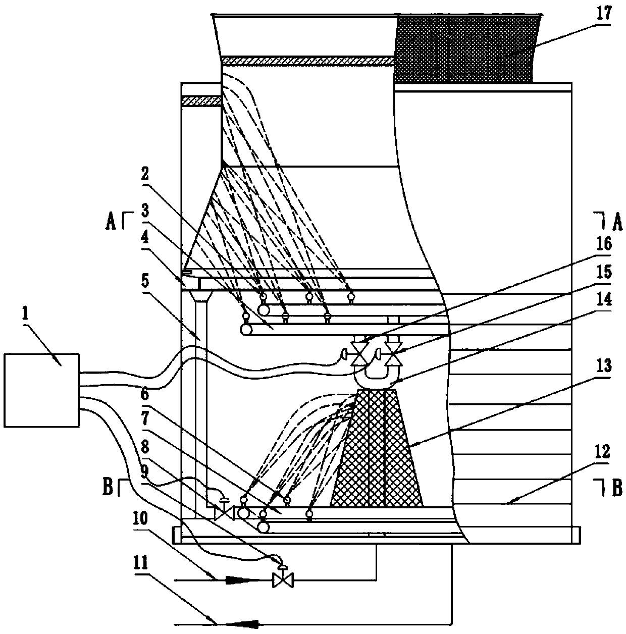
[0043] In order to solve the problems existing in the prior art, the embodiments of the present invention are as image 3 , attached Figure 4 And attached Figure 5 Shown: including the tower body, hot water inlet 10 pipes and cooling water outlet 11 pipes, the tower body is arranged in sequence from high to low with the top water distribution pipeline 3 in the middle and the top water distribution pipeline 7 in the bottom, and the top water distribution pipeline in the middle Road 3 is connected with a circumferentially distributed first-level multi-layer non-mechanical transmission fixed jet spray cooling nozzle group, and the bottom water distribution topological pipeline 7 is connected with a second-level multi-layer non-mechanical transmission fixed jet spray cooling nozzle group. There are 14 main water inlet pipes in communication between the water topology pipeline 3 and the bottom water distribution topology pipeline 7 . The hot water inlet 10 pipeline and the cool...

Embodiment 2

[0051] as attached Image 6 As shown, the difference between this embodiment and Embodiment 1 is that: the central water distribution topological pipeline 3 includes an inner ring and an outer ring, and the height of the inner ring is higher than that of the outer ring, and the height difference between the inner ring and the outer ring water distribution pipeline is designed by H1 The value is 600mm, and the water distribution pipelines of the inner ring and the outer ring adopt double-circuit four-channel water pipes.

[0052] The distance between any adjacent one-level multi-layer non-mechanical transmission fixed-jet spray cooling nozzles is L1, and the design of L1 is 800mm. is θ1, the design of θ1 is 85°, the angle between the one-level multi-layer non-mechanical transmission fixed jet spray cooling nozzle group and the horizontal direction is α, and the design of α is 30°.

[0053] The specific implementation process is as follows: due to the dual-circuit four-channel ...

Embodiment 3

[0055] as attached Figure 7As shown, the difference between this embodiment and the previous embodiment is that the bottom water distribution topological pipeline 7 includes an inner ring and an outer ring, and the height of the inner ring is higher than that of the outer ring, and the height difference H between the inner ring and the outer ring water distribution pipeline is 2 The design value is 300mm, and at the same time, the pipeline is arranged in a dual-circuit eight-channel uniform water inlet topology. The distance between any adjacent two-level multi-layer non-mechanical transmission fixed-jet spray cooling nozzle group is L2, and the design of L2 is 700mm. The angle between the first-level multi-layer non-mechanical transmission fixed-jet spray cooling nozzle group and the vertical direction is θ2 and θ2 are designed to be 80°, and the angle between the first-stage multi-layer non-mechanical transmission fixed jet spray cooling nozzle group and the horizontal dire...


PUM


Abstract

The invention discloses a mechanical transmission-free jet flow spray-adjustable cooling method and device, and belongs to the technical field of jet flow ventilation cooling. The device comprises a mechanical transmission-free jet flow spray-adjustable cooling device body, and a middle water distribution topological pipeline and a bottom water distribution topological pipeline are sequentially arranged at the position from the high position to the low position along the gravity potential energy of a pipeline system topological layout adopted a topological layout; and the middle water distribution topological pipeline is provided with first-stage multilayer mechanical transmission-free fixed jet spray cooling spray head sets which are distributed in the circumferential direction, secondarymultilayer mechanical transmission-free fixed jet spray cooling spray head sets are arranged on the bottom water distribution topological pipeline, and a main water inlet pipeline is in communicationwith the middle water distribution topological pipeline and the bottom water distribution topological pipeline. The mechanical transmission-free jet flow spray-adjustable cooling method and device aim to break through bottlenecks of the prior art and subvert the traditional design, the traditional mechanical transmission air draft part device is completely replaced with the water return pressure,and thus a stable and reliable maintenance-free cooling tower is formed.

Description

technical field [0001] The invention belongs to the technical field of jet ventilation and cooling, in particular to a non-mechanical transmission jet spray adjustable cooling method and device. Background technique [0002] At present, the existing technologies commonly used in the ventilation cooling tower industry are as follows: open counterflow cooling towers commonly used at home and abroad mainly include traditional mechanical ventilation packing cooling towers, traditional mechanical ventilation filling spray cooling towers, traditional hydraulic fans without filling gravity return Water secondary spray cooling tower. [0003] The traditional mechanical ventilation packing cooling tower is forced by an electric mechanical fan. This kind of cooling tower relies on packing cloth liquid mass transfer, drives the mechanical fan by electricity, has mechanical transmission deceleration parts, and has a packing structure. There are several major problems in the above techn...

Claims


Application Information

Patent Timeline
Patent Type & Authority Applications(China)
IPC IPC(8): F24F5/00F24F13/30F24F11/89F24F11/56
CPCF24F5/0035F24F11/56F24F11/89F24F13/30
Inventor 周明陈小康李俊魏仕英
Owner 重庆浪格节能环保科技有限公司
Why Eureka
Try Eureka