
Testing device and method of bending resistance of fiber materials by adopting double-end clamping three-bending method

A fiber material and testing device technology, applied in the direction of applying a stable bending force to test the strength of materials, measuring devices, and analyzing materials, can solve problems such as difficult bending force, fiber skew, slippage, etc., to improve reliability and Reproducibility, accurate and reliable instrument performance, and wide application range

Pending Publication Date: 2019-04-12
上海新纤仪器有限公司 +2
View PDF5 Cites 1 Cited by
  • Summary
  • Abstract
  • Description
  • Claims
  • Application Information

AI Technical Summary

Problems solved by technology

The cantilever beam method is only suitable for material samples with high stiffness, and cannot be used to measure the flexural properties of softer fiber material samples; the heart-shaped method is often used to test the flexural stiffness of fabrics, but this method is used to test When it comes to bending performance, because the fiber material is thin and soft, it is difficult to make a fiber material sample form a heart-shaped ring and measure its bending resistance; the three-point method or four-point method is generally used to measure the bending stiffness of hard materials. The material fiber has problems in sample preparation, sample placement and fixation, and external force point slippage, etc., and its research is still in the exploratory stage
In China, JQ03D single fiber tensile and compression bending instrument developed by Shanghai Zhongchen Digital Technology Equipment Co., Ltd. has studied the fiber bending test method. It is characterized in that one end of the fiber is fixed and the other end is free to rotate. The axial compression bending method called "one and a half bending", the problem of this method is that the fiber end may slip when it penetrates the microporous platform, the position of the fiber hinge end is difficult to determine, and the fiber protruding from the fixed end may be skewed Etc., the length of the fiber sample between the hinge end and the fixed end is different, resulting in a deviation in the measurement results of the fiber bending performance, affecting the accuracy and stability of the test results and failing to be practically popularized and applied.

Method used


Image

  • Testing device and method of bending resistance of fiber materials by adopting double-end clamping three-bending method
  • Testing device and method of bending resistance of fiber materials by adopting double-end clamping three-bending method

Examples


Embodiment Construction

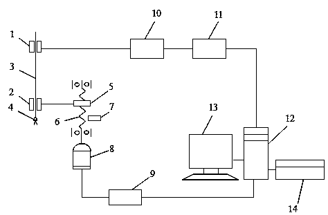
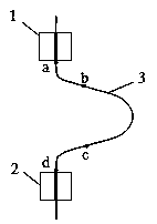
[0027] see figure 1 , 2 , which is a structural schematic diagram of a preferred embodiment of a fiber material bending resistance test device with double-end clamping and three-bending method of the present invention. As shown in the figure: it includes an upper holder 1 and a lower holder 2 with jaws for clamping the upper and lower ends of the sample 3 respectively; The counterweight that bears the initial tension and straightens under the action; the lower clamper 2 is driven by the driving mechanism to move up and down, and the lower clamper 2 is clamped between the upper clamper 1 and the lower clamper 3 during the upward movement The middle sample 3 can form a three-bend configuration; the upper holder 1 is connected with a load cell 10 .

[0028] In this embodiment, the counterweight is a tension clip 4 . When in use, the upper holder 1 clamps the upper end of the fiber material sample 3, and the tension clamp 4 clamps the other end of the fiber material sample 3, a...


PUM


Abstract

The invention relates to a testing device and method of bending resistance of fiber materials by adopting a double-end clamping three-bending method. The testing device comprises an upper clamp holder, a lower clamp holder and a counter weight, wherein the upper clamp holder and the lower clamp holder are provided with jaws and used for clamping the upper end and the lower end of a specimen separately, and the counter weight is fixed to the lower end of the specimen and enables the specimen to bear the initial tension to straighten under the action of gravity. The lower clamp holder is drivenby a driving mechanism to move up and down, and during the upward movement of the lower clamp holder, the specimen clamped between the upper clamp holder and the lower clamp holder to form a three-bending shape. The upper clamp holder is connected with a force sensor. The testing device is simple in structure and convenient to operate, the testing method using the device greatly improves the accuracy of testing results, the testing efficiency and the possibility of practical popularization and application, and the problem of testing the bending resistance of the fiber materials is solved successfully.

Description

technical field [0001] The invention belongs to the field of fiber material testing instruments and testing methods, in particular to a double-end clamping and three-bending fiber material bending resistance testing device and method. It is suitable for bending resistance quality inspection of chemical fiber filaments, optical fibers, hair and short fibers, product quality control, and bending performance analysis of various new fiber materials by research institutions. Background technique [0002] Fiber materials will be subjected to bending force during processing and its finished products, resulting in bending deformation. In the clothing textile industry, the filaments or yarns in the fabric are subjected to bending deformation to affect the softness and style of the fabric; in the home textile industry, the filaments are cut into short fibers and used as fillers to cover the outer fabric. The fibers are repeatedly bent and deformed by external forces. When the fibers ...

Claims


Application Information

Patent Timeline
Patent Type & Authority Applications(China)
IPC IPC(8): G01N3/20G01N3/04
CPCG01N3/04G01N3/20G01N2203/0023G01N2203/0435
Inventor 黄新林纪峰李汝勤吴林根方志良
Owner 上海新纤仪器有限公司
Learn More