Electrode locator for testing substation grounding grid based on global satellite navigation system

A technology for global satellite navigation and substation grounding grid, applied in the field of communications, can solve the problems of inability to meet the accuracy and repeatability of substation ground grid resistance measurement work, strict safety distance requirements, unfavorable erection of tower rulers, etc., and achieve fast and accurate data processing capabilities , Wide range of application, intuitive display of measurement results

Pending Publication Date: 2019-04-12
STATE GRID CORP OF CHINA +2
View PDF0 Cites 3 Cited by
  • Summary
  • Abstract
  • Description
  • Claims
  • Application Information

AI Technical Summary

Problems solved by technology

However, due to the large number of equipment intervals in the active substation, poor visibility, and strict safety distance requirements, it is not conducive to erecting tower feet. Therefore, this method is only applicable to new substations with good visibility and in the infrastructure construction stage.
[0016] (3) The newly released revised version "DL / T475-2017 Guidelines for the Measurement of Grounding Device Characteristic Parameters" requires that the grounding impedance test of large-scale grounding devices should be tested once every 5 to 6 years after the handover test is completed, which cannot be met by the existing technology Accuracy of substation ground grid resistance measurement work and repeatability of previous measurement positions in the same substation

Method used


Image

  • Electrode locator for testing substation grounding grid based on global satellite navigation system
  • Electrode locator for testing substation grounding grid based on global satellite navigation system
  • Electrode locator for testing substation grounding grid based on global satellite navigation system

Examples


Embodiment 2

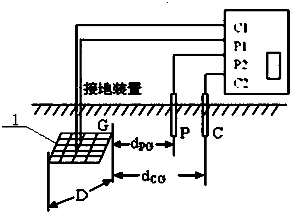
[0078] Embodiment 2, this embodiment is basically the same as Embodiment 1, the difference is that this embodiment is used to measure the grounding impedance of the substation grounding grid 1 for the second time, and determine the potential pole and current pole in the resistance test of the substation grounding grid 1 The piling position is used to assess the state of the grounding grid 1 of the substation, and its working process is:

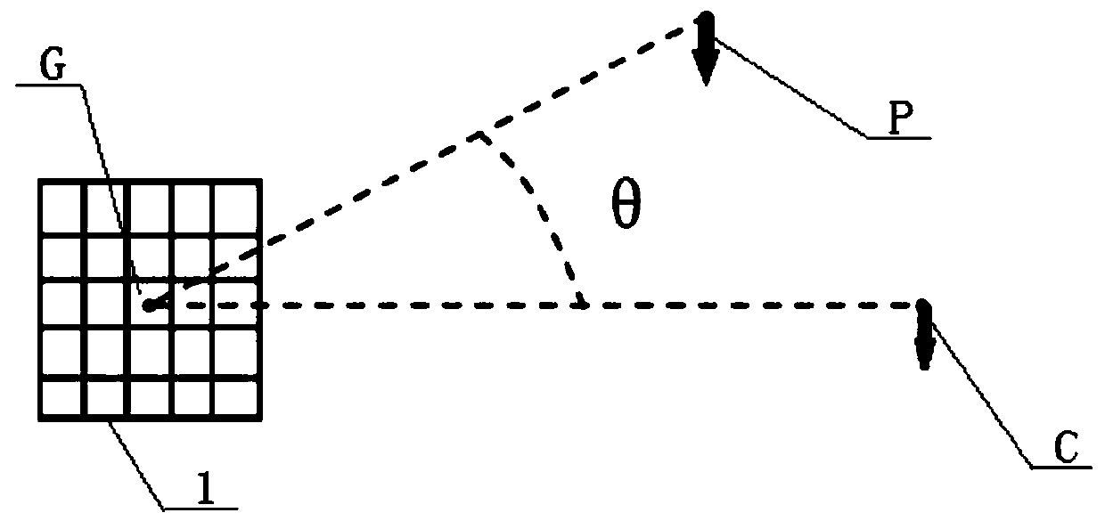
[0079] 1) First call out the longitude and latitude information of the grounding device position G of the substation grounding grid 1, the longitude and latitude information of the potential pile position P, the longitude and latitude information of the current pile position C and the included angle θ that are stored in the locator of this embodiment for the first time;

[0080] 2) According to the latitude and longitude information provided in step 1), receive the latitude and longitude information of the global satellite navigation system at...

Embodiment 3

[0085]Embodiment 3, this embodiment is basically the same as Embodiment 2, the difference is that this embodiment is used to repeatedly measure the grounding impedance of the substation grounding grid 1 for the third time, and the substation grounding grid 1 of the locator of this embodiment is called out first The grounding device position G of the grounding device, the latitude and longitude information of the potential pile position P, the latitude and longitude information of the current pile position C and the included angle θ, and then operate according to the steps 1) to 5) of the embodiment 2, and then the obtained substation grounding network 1 The grounding impedance value of the substation grounding grid 1 is compared with the grounding impedance value of the previous substation grounding grid 1 stored by the locator of this embodiment, the state of the substation grounding grid 1 is evaluated, and the obtained grounding device position G and potential pile position P...

Embodiment 4

[0086] Embodiment 4, this embodiment is basically the same as Embodiment 1, the difference is that this embodiment is used to simultaneously use two locators of this embodiment to initially determine the piling positions of the potential electrode and the current electrode in the resistance test of the substation grounding grid 1, Its working process is:

[0087] 1) When determining the piling positions of the potential pole and the current pole in the resistance test of the substation grounding grid 1 for the first time, two locators of this embodiment respectively receive the latitude and longitude information of the global satellite navigation system at the preliminarily scheduled reference point of the grounding device of the substation grounding grid 1 , perform the first positioning, and obtain the latitude and longitude information of the reference point of the grounding device of the substation grounding grid 1;

[0088] 2) One locator of this embodiment moves to the i...


PUM


Abstract

The invention relates to an electrode locator for testing a substation grounding grid based on a global satellite navigation system. The invention is characterized in that: the locator comprises a casing, a control panel, a single chip microcomputer module, a display module, a global satellite navigation system positioning module, a wireless communication module, and a power supply module. The control panel is arranged on the front surface of the casing. The single-chip microcomputer module, the display module, the global satellite navigation system positioning module, the wireless communication module, and the power supply module are arranged in the casing. The display screen of the display module is arranged on the control panel. The power supply module simultaneously supplies power to the control panel, the display module, the global satellite navigation system positioning module, the single-chip microcomputer module, and the wireless communication module. The electrode locator fortesting the substation grounding grid based on the global satellite navigation system has the advantages of simple structure, powerful function, small and flexible, convenient use, accurate positioning, wide application range, intuitive display, accurate precision, saving of time and labour, and high efficiency.

Description

technical field [0001] The invention relates to the communication field, and is a substation grounding grid test electrode locator based on a global satellite navigation system, which can determine the piling positions of potential poles and current poles in the substation grounding grid resistance test through the global satellite navigation system. Background technique [0002] The electrode positioning involved in the present invention refers to determining the position of the potential pole and the current pole when measuring the resistance of the substation grounding network, that is, the piling position of the voltage pile and the current pile. For the selection of the pile point position, see figure 1 . [0003] When calculating the resistance of the substation grounding grid, it is necessary to measure the straight-line distance d from the potential pole to the grounding device PG and the straight-line distance d from the current pole to the grounding device CG And...

Claims


Application Information

Patent Timeline
Patent Type & Authority Applications(China)
IPC IPC(8): G01S19/14G01S19/42G01R27/20
CPCG01S19/14G01R27/205G01S19/42
Inventor 葛猛蔺树全常群孙振胜杨伟龙迟作为姜成李哲张国超顾磊李棕陈若兴吕青峰
Owner STATE GRID CORP OF CHINA
Why Eureka
Try Eureka