Quasi-resonant staggered switched capacitor battery equalization circuit and control method thereof
A switching capacitor and battery equalization technology, applied in charge equalization circuits, battery circuit devices, secondary battery charging/discharging, etc., can solve the problems of slow equalization circuit equalization speed, etc., to improve equalization efficiency, small size, and reduce voltage effect of stress
- Summary
- Abstract
- Description
- Claims
- Application Information
AI Technical Summary
Problems solved by technology
Method used
Image
Examples
Embodiment 1
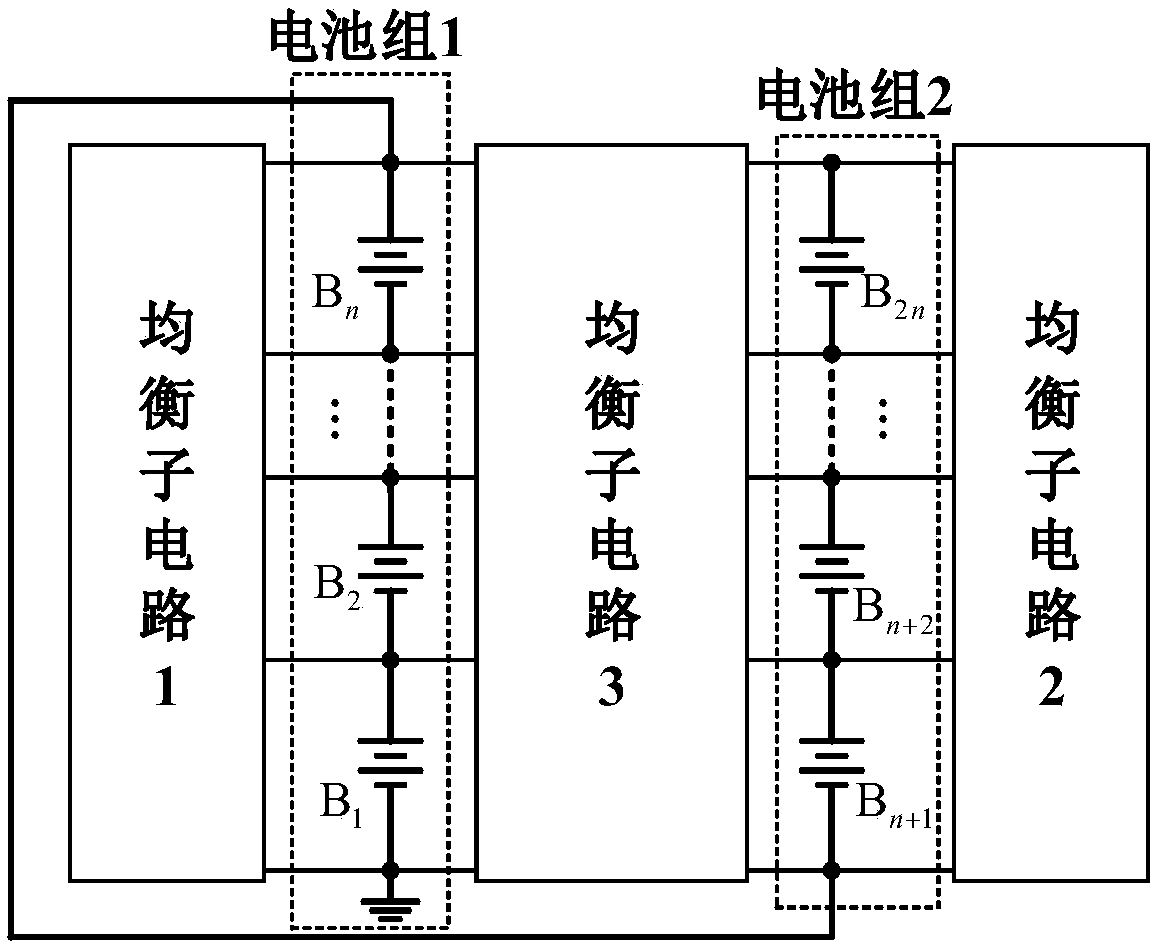
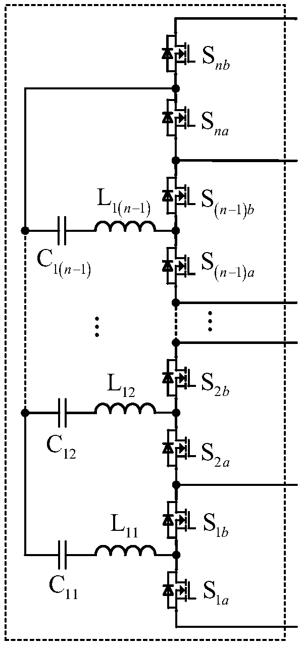
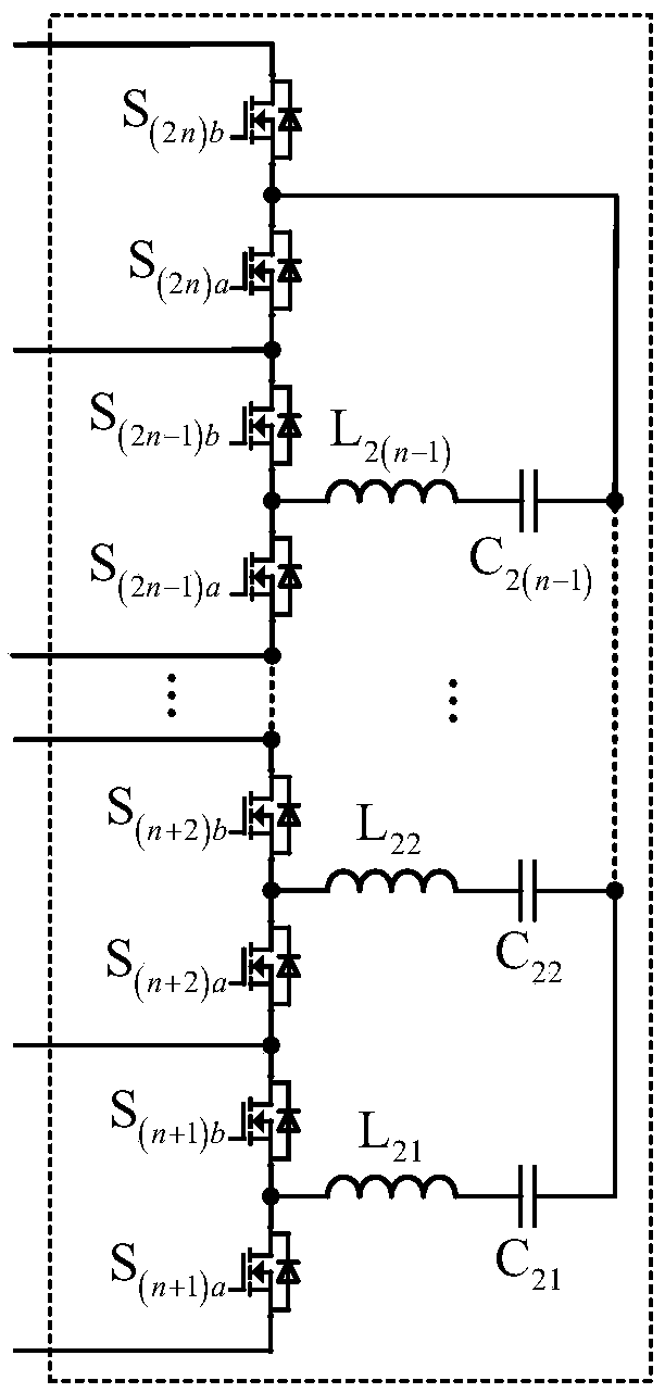
[0035] Taking the balancing circuit of 4 batteries as an example, its structure is as follows figure 2 shown. Without considering the dead time of the driving signal, the circuit equalization process has two working states, when the battery voltage V B1 >V B2 >V B3 >V B4 When , the circuit diagrams of the two working states of the circuit are as follows Figure 3a and 3b shown.
[0036] State A: drive signal V GSa When the level is high, the lower switching tube S corresponding to each battery inside the equalization sub-circuit 1 and equalization sub-circuit 2 1a , S 2a , S 3a , S 4a conduction, battery B 1 , B 3 to the balancing capacitor C 11 、C 21 Charging; the right switch tube S inside the equalization sub-circuit 3 a1 , S a2 , S a3 conduction, battery B 1 , B 2 to the balancing capacitor C 31 、C 32 Charge. At the same time, each balancing capacitor and the corresponding resonant inductor resonate, and when the inductor current resonates to zero, t...
Embodiment 2
[0041] Figure 8 It is the circuit structure diagram of the embodiment of the present invention with the balancing circuit of 8 batteries, Figure 9 for Figure 8 The simulation waveform of embodiment, simulation parameter is identical with embodiment 1, and initial voltage is V B1 =3.7V, V B2 =3.6V, V B3 =3.5V, V B4 =3.4V, V B5 =3.35V, V B6 =3.45V, V B7 =3.55V, V B6 = 3.65V. Depend on Figure 9It can be seen that with the increase of the equalization time, the voltages of the eight batteries in the battery pack are gradually approaching, and finally reach the equilibrium state, and the equalization time is 0.046s. Compared Figure 7 and Figure 8 It can be seen that the equalization time of 8 batteries and 4 batteries is basically the same, and the equalization speed has nothing to do with the number of batteries.
[0042] In summary, the quasi-resonant interleaved switched capacitor battery equalization circuit proposed by the present invention has simple struct...
PUM
 Abstract
Description
Claims
Application Information
 - R&D
- Intellectual Property
- Life Sciences
- Materials
- Tech Scout
- Unparalleled Data Quality
- Higher Quality Content
- 60% Fewer Hallucinations
Browse by: Latest US Patents, China's latest patents, Technical Efficacy Thesaurus, Application Domain, Technology Topic, Popular Technical Reports.
© 2025 PatSnap. All rights reserved.Legal|Privacy policy|Modern Slavery Act Transparency Statement|Sitemap|About US| Contact US: help@patsnap.com


