Reluctance machine with laminated connection type stators and fabrication method of reluctance machine

A reluctance motor and manufacturing method technology, applied in the manufacture of stator/rotor bodies, magnetic circuits, electromechanical devices, etc., can solve the problems of blocked electromagnetic field circuits, low material utilization, and reduced motor efficiency, so as to achieve smooth magnetic circuits and reduce Production cost, effect of improving motor efficiency

Inactive Publication Date: 2019-04-12
ZHEJIANG SPECIAL ELECTRIC MOTOR CO LTD
View PDF4 Cites 2 Cited by
  • Summary
  • Abstract
  • Description
  • Claims
  • Application Information

AI Technical Summary

Problems solved by technology

This blanking method has a lot of leftovers, resulting in a very low material utilization rate
[0005] The pre-set stator stampings used in general motors are bent into a ring shape by the linear yoke. The cracks of the electromagnetic field will cause the circuit of the electromagnetic field to be blocked, resulting in serious magnetic flux leakage, thereby reducing the efficiency of the motor

Method used


Image

  • Reluctance machine with laminated connection type stators and fabrication method of reluctance machine
  • Reluctance machine with laminated connection type stators and fabrication method of reluctance machine
  • Reluctance machine with laminated connection type stators and fabrication method of reluctance machine

Examples


Embodiment Construction

[0030] The present invention will be described in detail below in conjunction with the accompanying drawings and embodiments.

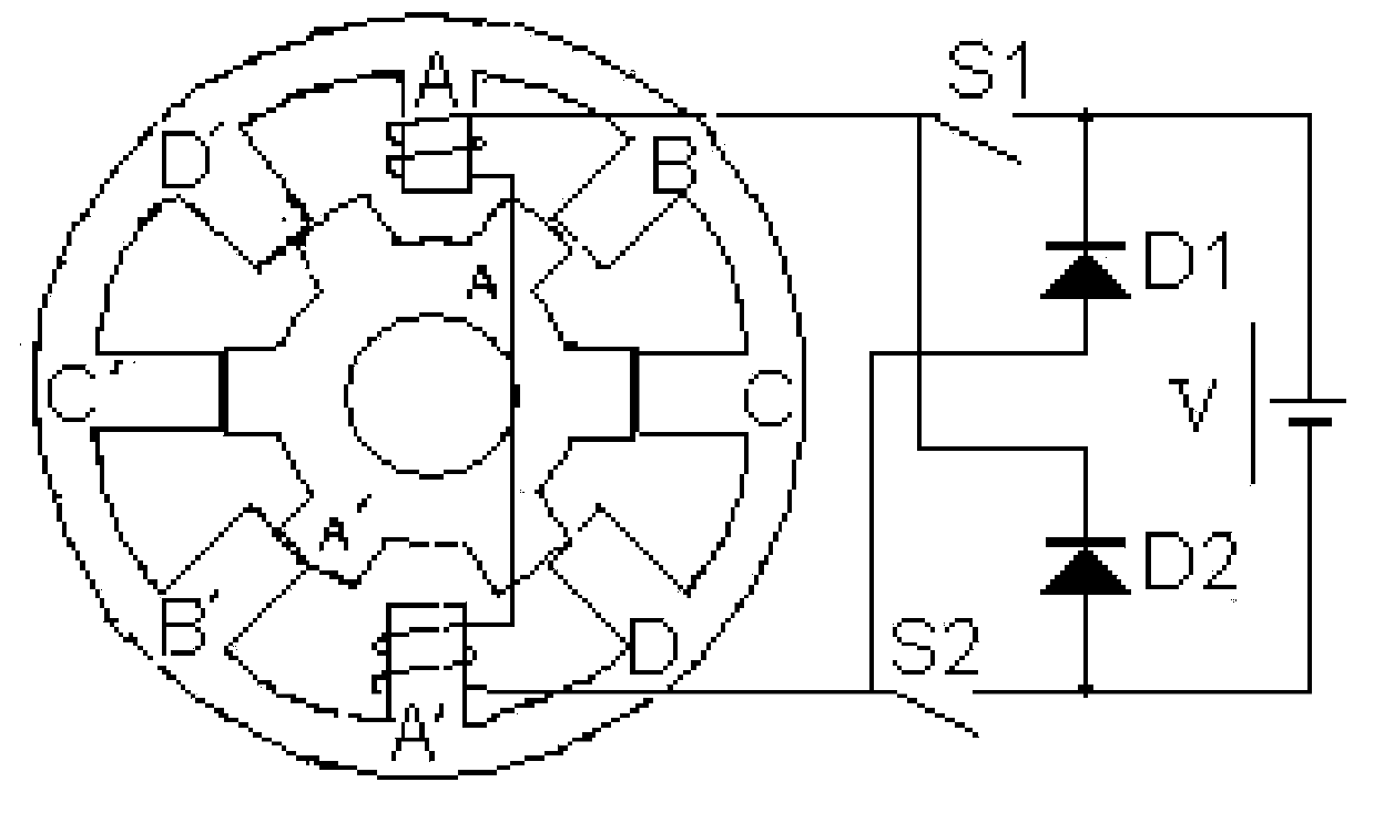
[0031] In a specific embodiment, the reluctance motor of the present invention may be a double-salient pole variable reluctance motor, and the salient poles of the rotor are formed by laminating ordinary silicon steel sheets of a lower grade. The rotor has neither windings nor permanent magnets. The stator poles are wound with concentrated windings. The two radially opposite windings are connected together, which is called "one phase". The switched reluctance motor can be designed into a variety of different phase structures, and the fixed , There are many different collocations for the number of poles of the rotor. The number of phases is large and the step angle is small, which is beneficial to reduce torque ripple, but the structure is complex, and there are many main switching devices, and the cost is high. Nowadays, the four-phase 8 / 6 structure a...


PUM


Abstract

The invention discloses a reluctance machine. The reluctance machine comprises multiple layers of stator cores and multiple layers of rotor cores which are formed in a lamination way, the reluctance machine is characterized in that each stator core is formed by laminating a first punching sheet and a second punching sheet in a staggered way, the first punching sheet and the second punching sheet are inserted to each other and are cut in a suit way, the first punching sheet and the second punching sheet respectively comprises N punching sheet units which are connected by connection parts, eachpunching sheet unit comprises a yoke part and a tooth part, mutual surfaces of adjacent yoke parts after ring formation are in contact to form a gap, gaps of adjacent layers are not in the same axialcross section, and a salient pole of a rotor is made of a magnetic conduction material of which the quality is lower than that of a stator. The reluctance machine is good in manufacturing process andhas the advantage of automatic manufacturing on a large scale; and moreover, the performance of the reluctance machine is improved, the material utilization rate is improved, and the motor cost is reduced.

Description

technical field [0001] The invention relates to the field of motors, in particular to a reluctance motor with an overlap-connected stator and a preparation method. Background technique [0002] The motor is a device that converts electromechanical energy through the medium of a magnetic field. With the rapid development of modern science and technology, especially the development of microelectronics technology, power electronics technology, automatic control technology and material science, many special motors based on new principles with superior performance have emerged. The reluctance motor is a new type of speed-regulating motor with electromechanical integration. The speed-regulating system has the advantages of both DC and AC speed-regulating systems. speed system. The structure and working principle of the reluctance motor are very different from the traditional AC and DC motors, which use the principle of minimum reluctance to form magnetic pull. Because of its si...

Claims


Application Information

Patent Timeline
Patent Type & Authority Applications(China)
IPC IPC(8): H02K1/16H02K15/02
CPCH02K1/165H02K15/02H02K2213/03
Inventor 吕仲维童永钢傅志华张伟青
Owner ZHEJIANG SPECIAL ELECTRIC MOTOR CO LTD
Why Eureka
Try Eureka