Plasma synthetic jet actuator with low Reynolds number

A plasma, low Reynolds number technology, applied in the direction of plasma, affecting the air flow flowing through the surface of the aircraft, aircraft parts, etc., can solve the problems that restrict the application of plasma synthetic jet exciters and the high jet velocity, and reach the applicable range The effect of increasing, high control frequency and large control range

Active Publication Date: 2019-04-12
HARBIN INST OF TECH
View PDF12 Cites 5 Cited by
  • Summary
  • Abstract
  • Description
  • Claims
  • Application Information

AI Technical Summary

Problems solved by technology

However, the existing plasma synthetic jet actuators have a high jet velocity and are difficult to use under low Reynolds number conditions, which restricts the application of plasma synthetic jet actuators in the field of low Reynolds number airfoil flow control

Method used


Image

  • Plasma synthetic jet actuator with low Reynolds number
  • Plasma synthetic jet actuator with low Reynolds number
  • Plasma synthetic jet actuator with low Reynolds number

Examples


specific Embodiment 1

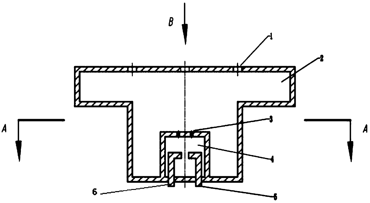
[0033] according to figure 1 As shown, a plasma synthetic jet exciter under low Reynolds number conditions includes exciter discharge chamber 4, exciter buffer chamber 2, cathode discharge electrode 6, anode discharge electrode 5 and heat-resistant silica gel, and exciter discharge chamber 4 is placed In the exciter buffer chamber 2;

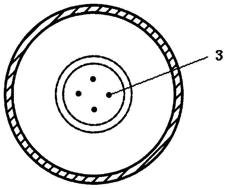
[0034] The exciter discharge chamber 4 is a hollow cylinder, the exciter buffer chamber 2 is a hollow cylinder or a hollow cylinder with a polygonal geometric section in cross section, and an array distribution is arranged on the partition plate between the exciter discharge chamber 4 and the exciter buffer chamber 2 The high-speed jet hole 3, the upper wall of the exciter buffer cavity 2 is provided with a low-speed jet hole 1 or a slot opening.

[0035] The body wall of the discharge chamber 4 of the exciter and the heat-resistant silica gel are both insulating materials. The discharge electrode is connected to the discharge chamber 4 of the ...

specific Embodiment 2

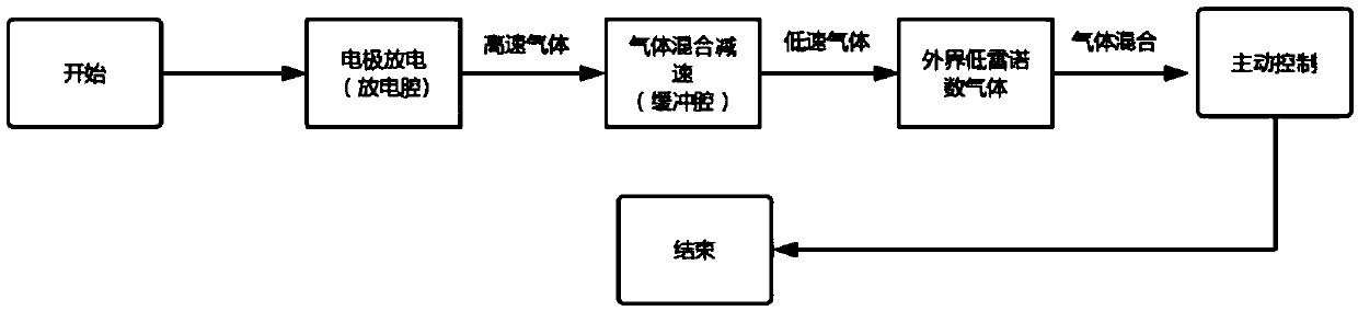
[0038] according to figure 2 As shown, the working principle of the low Reynolds number plasma synthetic jet actuator is: the gas in the discharge chamber is heated under the discharge action of the cathode discharge electrode 6 and the anode discharge electrode 5, so that the gas in the discharge chamber becomes a high-pressure state, and the high-speed gas From the high-speed jet hole 3 to the actuator buffer cavity 2, the high-speed gas is decelerated in the actuator buffer cavity 2 to become a low-speed gas, and then the gas is injected from the low-speed jet hole 1, the shape and size of the actuator buffer cavity 2 and the internal guide The structure and the shape and size of the low-velocity jet hole 1 determine the gas velocity of the jet to the outside, and the air flow to the outside exchanges momentum with the outside gas to achieve an active control effect. The exciter buffer chamber 2 can also be a cylinder whose cross section is a polygonal geometric section ex...


PUM


Abstract

The invention discloses a plasma synthetic jet actuator with low Reynolds number. The plasma synthetic jet actuator comprises an actuator discharge cavity (4), an actuator buffer cavity (2), a cathodedischarge electrode (6), an anode discharge electrode (5) and heat-resistant silica gel. The actuator discharge cavity (4) is placed inside the actuator buffer cavity (2), and the heat-resistant silica gel is used for fixing and sealing the cathode discharge electrode (6) and the anode discharge electrode (5) at the bottom of the actuator discharge cavity (4). Under the effect of the discharge electrodes, gas inside the actuator discharge cavity (4) becomes high-speed gas, the high-speed gas is ejected into the actuator buffer cavity (2) through high-speed jet holes (3), the high-speed gas becomes low-speed gas through speed reduction, the low-speed gas is ejected to the outside through low-speed jet holes (1), and finally low-speed gas with the Re of no more than 10<-6> are ejected inside the actuator buffer cavity (2). The plasma synthetic jet actuator is simple in structure, high in stability, high in efficiency and small in volume.

Description

technical field [0001] The invention relates to the field of active flow control of low Reynolds number airfoil flow, and is a plasma synthetic jet exciter under low Reynolds number conditions. Background technique [0002] The flow control of a typical airfoil is a key issue in the aviation field. Its main purpose is to solve the aircraft stall caused by flow separation. Delaying flow separation and increasing the critical angle of attack are its core tasks. In the future battlefield, the trend dominated by UAV (unmanned aerial vehicle) is becoming increasingly prominent. And as special operations and urban missions continue to reduce the size of UAVs, micro aerial vehicle MAV, (micro aerial vehicle) came into being. [0003] Compared with traditional aircraft, UAVs or MAVs are generally smaller or miniature, and their flight speeds are lower, and most of them exhibit low Reynolds number flight characteristics. Therefore, the flow separation stall phenomenon that is very ...

Claims


Application Information

Patent Timeline
Patent Type & Authority Applications(China)
IPC IPC(8): H05H1/30B64C23/00
CPCB64C23/005H05H1/30
Inventor 李彪周德力蔡伟华
Owner HARBIN INST OF TECH
Why Eureka
Try Eureka