Roller coaster device

A roller coaster and frame technology, which is applied in the field of large-scale amusement facilities for roller coasters, can solve the problems that it is difficult to ensure the structural strength and safety of the frame, affect the overall service life of the frame bridge, and affect the overall strength of the frame, so as to reduce bumps and vibrations , collision and vibration prolongation, the effect of improving the service life

Active Publication Date: 2019-04-16
北京中冶设备研究设计总院有限公司
View PDF9 Cites 2 Cited by
  • Summary
  • Abstract
  • Description
  • Claims
  • Application Information

AI Technical Summary

Problems solved by technology

[0004] In the above-mentioned roller coaster structure in the prior art, the car body is mostly connected to the bridge frame through a single vertical shaft, and then the rear bridge frame is connected and fixed with the above-mentioned wheel train. It has been found in long-term operation and practice that such The connection means that the wheel trains on both sides of the roller coaster structure must always maintain the same rotation angle during the cornering process. In this way, as the complexity of the roller coaster track increases again and again, when the roller coaster has complex curve design and frequent steering changes When driving on the roller coaster track, the two wheel trains connected by a single vertical shaft are difficult to concentrate due to the bending moment, and the stress is not good, which in turn affects the overall strength of the frame, and it is difficult to ensure the structural strength of the frame during long-term driving. and security
[0005] On the other hand, the braking system structure adopted by the roller coaster in the prior art is relatively single, it is difficult to maintain a stable deceleration during the deceleration process of the train, and the roller coaster structure is easy to produce larger bumps or vibrations in the braking process. And vibration will not only increase the safety hazards of passengers during the braking process, but also cause damage to the overall structure of the frame, which in turn affects the overall service life of the frame and bridge

Method used


Image

  • Roller coaster device
  • Roller coaster device

Examples


Embodiment Construction

[0016] Embodiments of the roller coaster device according to the present invention will be described below with reference to the accompanying drawings. As those skilled in the art would realize, the described embodiments may be modified in various different ways, all without departing from the spirit and scope of the present invention. Accordingly, the drawings and description are illustrative in nature and not intended to limit the scope of the claims. Also, in this specification, the drawings are not drawn to scale, and like reference numerals denote like parts.

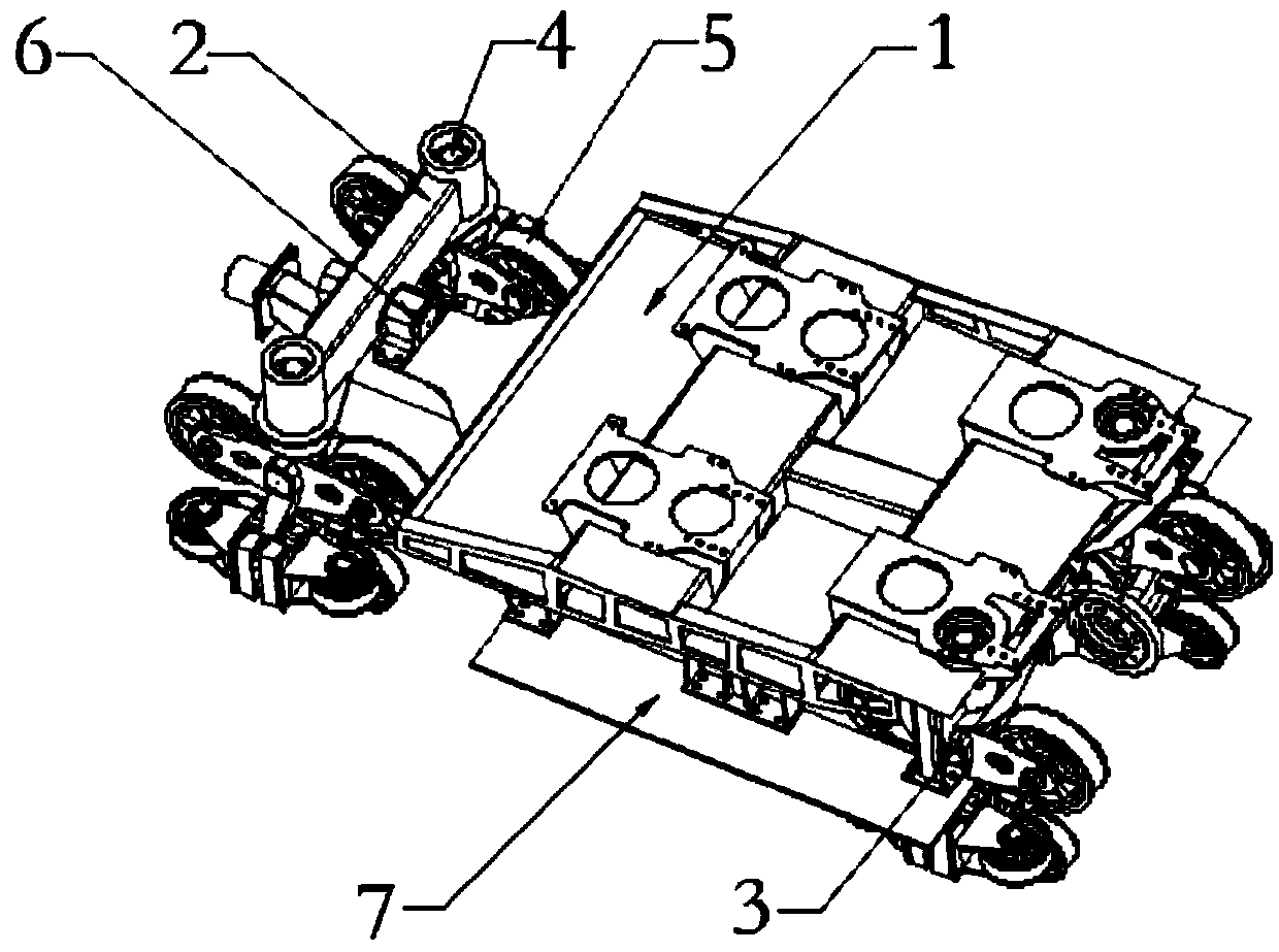
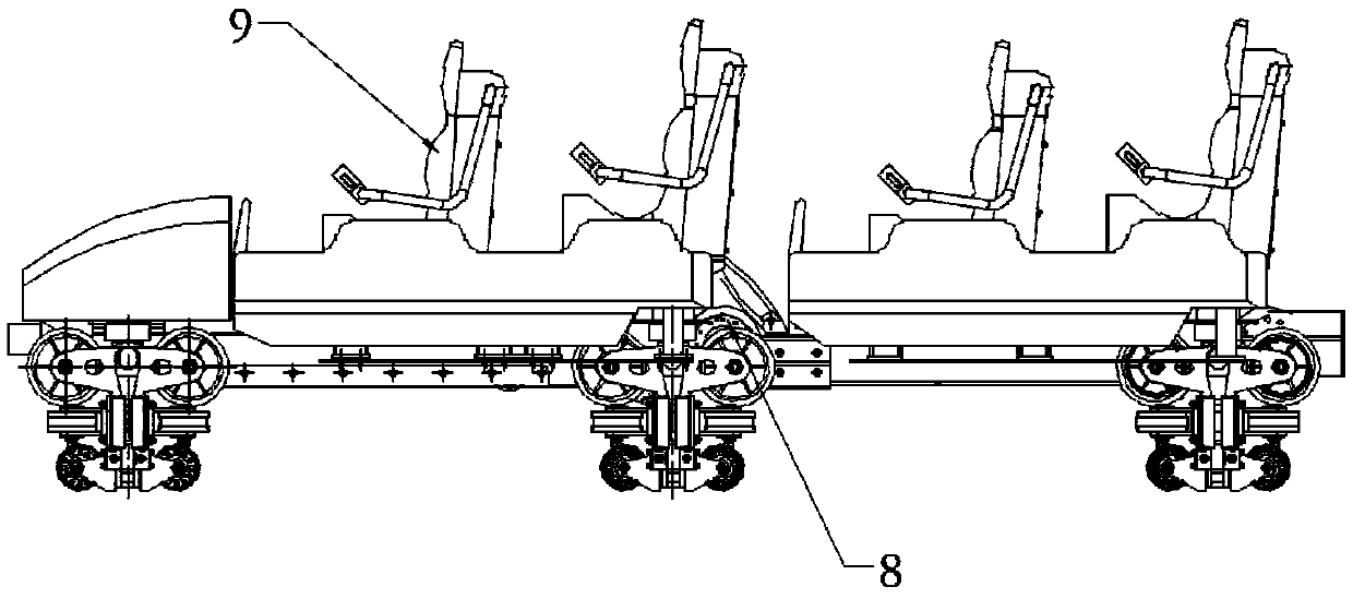
[0017] figure 1 It is a schematic diagram showing the structure of the roller coaster device described in one embodiment of the present invention. figure 2 It is a side view, showing the side view structure of the train unit connection and fixing in the roller coaster device described in this embodiment of the present invention. Such as figure 1 and figure 2 As shown, the roller coaster device described in t...


PUM


Abstract

The invention provides a roller coaster device, which comprises a plurality of train units which are sequentially connected, wherein the train units comprise a frame, wherein the frame is horizontallyarranged; a bridge frame, the bridge frame is arranged at the front end of the frame and is connected with the frame, the bridge frame comprises concave'-shaped connectors, two ends of each connectorare respectively provided with a vertical shaft, and the vertical shaft is used for being connected and fixed with a gear train; a tail seat, the tail seat is arranged at the central position of thetail part of the frame, a gear train which is consistent with the vertical shaft is fixed on the tail seat, the tail seat is used for mounting a spherical hinge connector, and the tail seat is connected with a plurality of train units through the spherical hinge connector. The roller coaster device has the advantages of simple structure, easy realization, capability of improving the integral stress intensity of the roller coaster, capability of respectively keeping independent rotation angles of the gear train in the direction changing or track changing process, ensuring uniform stress distribution of the gear trains, enabling the roller coaster to run on the tracks with sufficient degrees of freedom, so that the driving safety and the service life of the roller coaster device are furtherimproved.

Description

technical field [0001] The invention relates to a roller coaster large-scale amusement facility, in particular to a roller coaster device. Background technique [0002] Large roller coasters are common amusement facilities in large amusement parks, which mainly include trains, driving tracks, columns, traction systems and braking systems. The operating principle of the roller coaster is that the traction system pulls the train to the highest point of the running track, and then the traction system is separated from the train, and then the train runs quickly along the running track under the action of its own gravity and inertia, relying on the mutual transformation of its own potential energy and kinetic energy , and finally the braking system operates, causing the train to decelerate and return to the station. [0003] The train is multi-section, and each train unit is connected by a connector, and each unit is connected to the bridge frame through a wheel train. In this w...

Claims


Application Information

Patent Timeline
Patent Type & Authority Applications(China)
IPC IPC(8): A63G21/06
CPCA63G21/06
Inventor 孙亚伟王国平张金利黄羽孟洁
Owner 北京中冶设备研究设计总院有限公司
Why Eureka
Try Eureka