Tool mold for high-speed railway part casting

A technology for high-speed railways and parts, applied in the direction of manufacturing tools, casting equipment, casting molding equipment, etc., can solve the problems of low reliability, easy generation of micro-bubbles, and low practicability, so as to improve the reliability of use, facilitate fixing and Mold opening, effect of improving practicability

Inactive Publication Date: 2019-04-16
上海汇警市政工程有限公司
View PDF6 Cites 5 Cited by
  • Summary
  • Abstract
  • Description
  • Claims
  • Application Information

AI Technical Summary

Problems solved by technology

[0002] As we all know, tooling, that is, process equipment: refers to the general term for various tools used in the manufacturing process, including tools / fixtures / molds / measuring tools / checking tools / auxiliary tools / fitter tools / station tools, etc. Tooling is its general abbreviation, with The high-speed railway parts casting tooling mold is an auxiliary device used in the production process of high-speed railway parts to assist its casting and molding. It has been widely used in the field of mechanical processing; the existing high-speed railway parts The component casting tooling mold includes a mold body, the interior of the mold body is provided with a mold cavity, and the top of the mold body is provided with a pouring port communicating with the mold cavity; The pouring port is introduced into the mold cavity, and the mold is opened after the molten metal is formed in the cavity and the processed parts are taken out; it is found in the use of the existing tooling molds for high-speed railway parts casting that the molten metal is self-contained by the pouring port. When it is introduced into the mold cavity, the impact force is relatively large, and micro-bubbles are likely to be generated, which affects the quality of the workpiece molding, resulting in low practicability; and it is necessary to tighten the screws to fix the upper and lower molds of the mold body during pouring, which is cumbersome to operate, resulting in reliable use. lower sex

Method used


Image

  • Tool mold for high-speed railway part casting
  • Tool mold for high-speed railway part casting
  • Tool mold for high-speed railway part casting

Examples


Embodiment Construction

[0017] The specific implementation manners of the present invention will be further described in detail below in conjunction with the accompanying drawings and embodiments. The following examples are used to illustrate the present invention, but are not intended to limit the scope of the present invention.

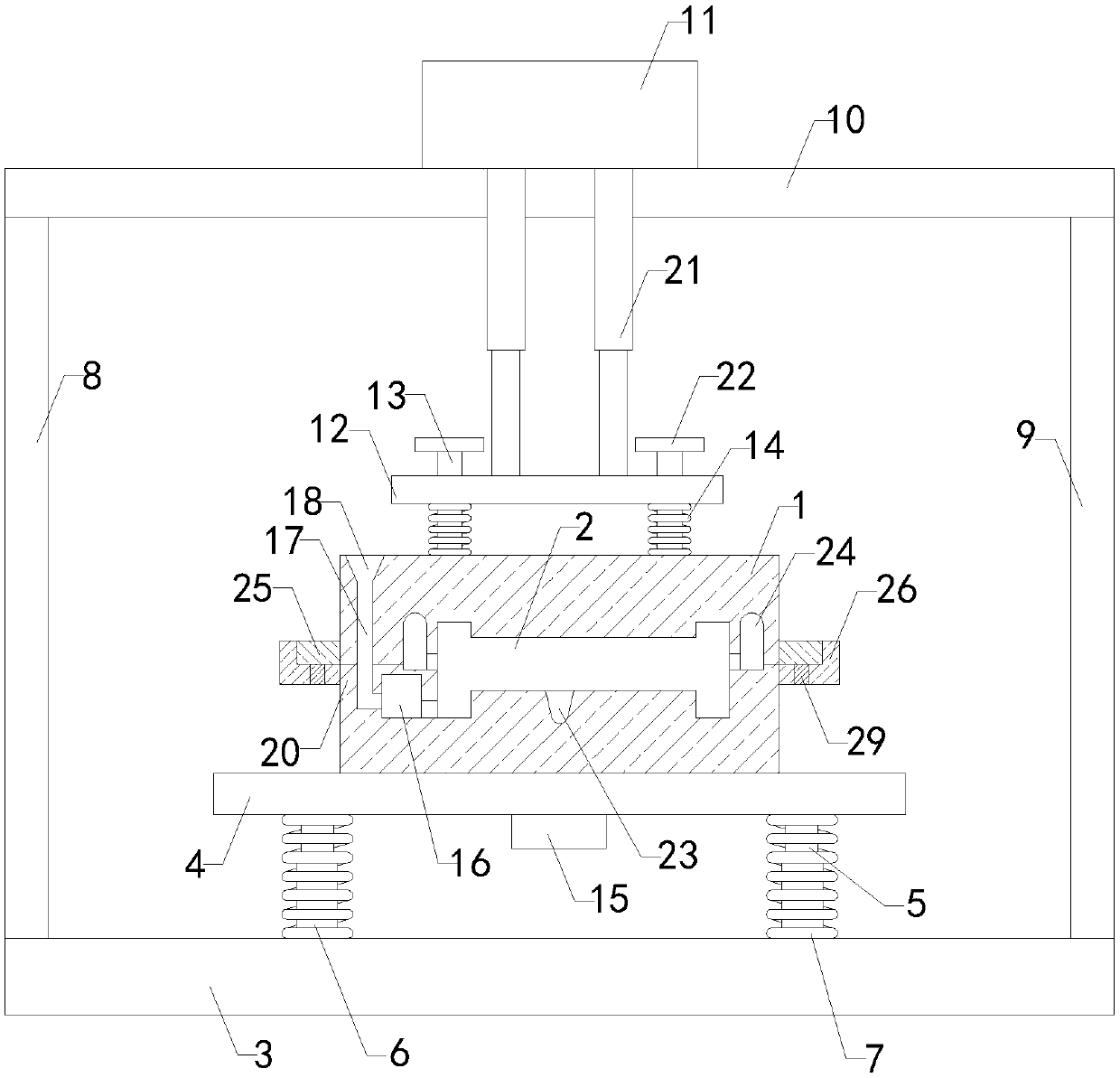
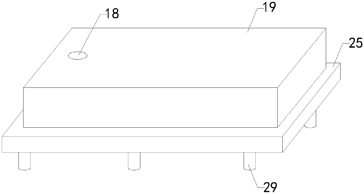
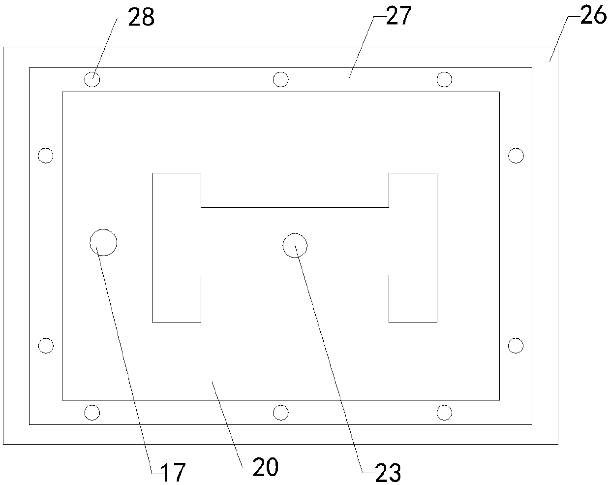
[0018] like Figure 1 to Figure 3 As shown, a kind of casting tooling mold for high-speed railway parts of the present invention includes a mold body 1, and the inside of the mold body 1 is provided with a mold cavity 2; it also includes a workbench 3, a support plate 4, four groups of guide pillars 5, Four sets of guide sleeves 6, four sets of support springs 7, left support plate 8, right support plate 9, top plate 10, biaxial cylinder 11, connecting plate 12, four sets of limit rods 13 and four sets of compression springs 14, four sets The bottom ends of the guide sleeves 6 are respectively connected to the left front side, right front side, left rear side and right re...


PUM


Abstract

The invention relates to the technical field of part casting auxiliary devices, in particular to a tool mold for high-speed railway part casting; and the tool mold can effectively prevent the condition of generation of micro bubbles due to impact force when molten metal is guided into a mold cavity, guarantees the workpiece molding quality, improves the practicability, is convenient to fix and open a mold main body, is convenient to operate, and improves the use reliability. The tool mold comprises the mold main body; the mold cavity is formed in the mold main body; a buffer pack and a pouringgate are arranged in the mold main body; a casting port is formed in the top end of the mold main body; the top end of the pouring gate communicates with the casting port; the bottom end of the pouring gate communicates with the buffer pack; and the buffer pack communicates with the mold cavity. The tool mold further comprises a worktable, a support plate, four sets of guide columns, four sets ofguide sleeves, four sets of support springs, a left support plate, a right support plate, a top plate, a double-shaft cylinder, a connecting plate, four sets of limiting rods, four sets of pressing springs, a vibrator, a piston rod and four sets of limiting plates.

Description

technical field [0001] The invention relates to the technical field of parts casting processing attachments, in particular to a tooling mold for high-speed railway parts casting. Background technique [0002] As we all know, tooling, that is, process equipment: refers to the general term for various tools used in the manufacturing process, including tools / fixtures / molds / measuring tools / checking tools / auxiliary tools / fitter tools / station tools, etc. Tooling is its general abbreviation, with The high-speed railway parts casting tooling mold is an auxiliary device used in the production process of high-speed railway parts to assist its casting and molding. It has been widely used in the field of mechanical processing; the existing high-speed railway parts The component casting tooling mold includes a mold body, the inside of the mold body is provided with a mold cavity, and the top of the mold body is provided with a pouring port communicating with the mold cavity; The pouring...

Claims


Application Information

Patent Timeline
Patent Type & Authority Applications(China)
IPC IPC(8): B22C9/08B22D27/08B22D33/04B22D27/06
CPCB22C9/082B22C9/088B22D27/06B22D27/08B22D33/04
Inventor 司长江
Owner 上海汇警市政工程有限公司
Why Eureka
Try Eureka