A continuous biomass pyrolysis gasification device and method

A technology of pyrolysis gasification and biomass, applied in gasification process, production of combustible gas, energy input, etc., can solve the problems of high gasification energy consumption, high gasification efficiency, poor gasification efficiency, etc., and achieve heat exchange Effect of large area, high gasification reaction activity, and shortened reaction time

Active Publication Date: 2020-12-29
HUAZHONG UNIV OF SCI & TECH
View PDF11 Cites 0 Cited by
  • Summary
  • Abstract
  • Description
  • Claims
  • Application Information

AI Technical Summary

Problems solved by technology

[0007] In view of the above defects or improvement needs of the prior art, the present invention provides a continuous biomass pyrolysis gasification device and method, aiming to solve the problems of low gas quality and poor gasification efficiency in the existing biomass gasification process , high gasification energy consumption and other issues, the device can continuously produce biomass gas with low tar and low dust content, and the calorific value of the gas is easy to adjust, the physical heat of the gasification system is utilized in stages, and the waste heat of flue gas and ash is fully recycled. The biomass is fully utilized, the gasification energy consumption is low, the gasification efficiency is high, and it is suitable for preparing biomass gas with different calorific values, low tar and low dust content for various purposes

Method used


Image

  • A continuous biomass pyrolysis gasification device and method
  • A continuous biomass pyrolysis gasification device and method
  • A continuous biomass pyrolysis gasification device and method

Examples


Embodiment Construction

[0034] In order to make the object, technical solution and advantages of the present invention clearer, the present invention will be further described in detail below in conjunction with the accompanying drawings and embodiments. It should be understood that the specific embodiments described here are only used to explain the present invention, not to limit the present invention. In addition, the technical features involved in the various embodiments of the present invention described below can be combined with each other as long as they do not constitute a conflict with each other.

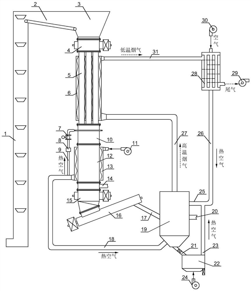
[0035] Such as figure 1 As shown, a continuous biomass pyrolysis gasification device provided by the embodiment of the present invention includes a feeding unit, a pyrolysis unit, a gasification unit, a heat exchange unit and a combustion unit arranged in sequence, wherein the feeding unit is used for The biomass raw material is sent to the pyrolysis unit, and the biomass raw material is pyroly...


PUM

PropertyMeasurementUnit
diameteraaaaaaaaaa

Abstract

The invention belongs to the field of biomass energy, and discloses a continuous biomass pyrolysis gasification device and method. The device comprises a feeding unit, a pyrolysis unit, a gasificationunit, a heat exchange unit and a combustion unit which are arranged in sequence; the feeding unit sends biomass into the pyrolysis unit for pyrolysis to produce coke and volatile matter, the coke andthe volatile matter are subjected to a gasification reaction in the gasification unit to produce combustible gas and gasification residues, the combustible gas and the gasification residues exchangeheat with air in the heat exchange unit, hot air is partially sent into the gasification unit, the other part of hot air is sent into the combustion unit, the combustible gas after heat exchange is sent out from the heat exchange unit, the gasification residues after heat exchange are conveyed into the combustion unit for combustion, high-temperature flue gas generated by the combustion is conveyed to the pyrolysis unit and exchanges heat with the biomass to become low-temperature flue gas, and the low-temperature flue gas and ash generated by the combustion are utilized for heating air to make the heated air serve as secondary air of the combustion unit. By means of the continuous biomass pyrolysis gasification device and method, the gradient utilization of physical heat can be achieved,the waste heat of the flue gas and the ash is fully recycled and utilized, the biomass is completely utilized, the energy consumption for gasification is low, and the gasification efficiency is high.

Description

technical field [0001] The invention belongs to the field of biomass energy, and more specifically relates to a continuous biomass pyrolysis gasification device and method. Background technique [0002] Biomass is a fast, renewable and clean energy with a huge amount and is environmentally friendly. Biomass gasification is used to convert it into gas fuel to replace fossil energy such as coal and natural gas, which can reduce NO X / SO X Pollutant emissions, alleviating smog problems, and realizing CO 2 Zero emission, the application prospect is very broad. In recent years, biomass gasification technology has been vigorously developed, and has initially entered the stage of large-scale application. The existing commercial operation technologies mainly include biomass gasification power generation, centralized gas supply and heating, and synthesis gas preparation. During the operation, there were problems such as difficult control of gas quality (composition, calorific valu...

Claims


Application Information

Patent Timeline
Patent Type & Authority Patents(China)
IPC IPC(8): C10J3/60C10J3/66C10J3/72C10J3/84
CPCC10J3/60C10J3/66C10J3/72C10J3/723C10J3/84C10J2300/0916C10J2300/1606C10J2300/1869Y02P20/129
Inventor 陈汉平谢迎谱杨海平刘标胡俊豪曾阔邵敬爱杨晴陈应泉王贤华张世红
Owner HUAZHONG UNIV OF SCI & TECH
Why Eureka
Try Eureka