Split type hydraulic pile hammer

A hydraulic piling hammer, split-type technology, applied in the direction of sheet pile wall, building, foundation structure engineering, etc., can solve the problems of transfer transportation cost and manufacturing cost increase, hydraulic impact hammer striking efficiency decrease, pile cap production and transportation troubles, etc. , to achieve the effect of reducing volume and quality, reducing manufacturing cost and operating cost, and improving pile sinking efficiency

Pending Publication Date: 2019-04-16
JIANGSU JUWEI MACHINERY
View PDF0 Cites 0 Cited by
  • Summary
  • Abstract
  • Description
  • Claims
  • Application Information

AI Technical Summary

Problems solved by technology

There are many obvious deficiencies in the hydraulic piling hammer of this structure: first, the pile caps applied to large-diameter pipe piles must be very large in volume and size, and the weight of a single pile cap is more than a hundred tons, and the production and transportation of the pile caps are difficult. It is more troublesome; especially the impact force of the hammer head is along the direction of the centerline of the barrel pile and not the position of the wall of the barrel pile, so the impact force of the hammer head is transmitted to the wall of the barrel pile through the top surface of the pile cap, which not only requires the pile The cap has sufficient rigidity and strength, and the elastic deformation of the pile cap during the impact of the hammer will consume a lot of striking energy, so that the striking efficiency of the hydraulic impact hammer is significantly reduced; moreover, to increase the striking energy of this type of pile hammer, the pile must be increased. The weight of the hammer and its hammer head, and the increase in the weight of a single pile hammer and hammer head has brought a substantial increase in transfer transportation costs and manufacturing costs

Method used


Image

  • Split type hydraulic pile hammer
  • Split type hydraulic pile hammer
  • Split type hydraulic pile hammer

Examples


Embodiment 2

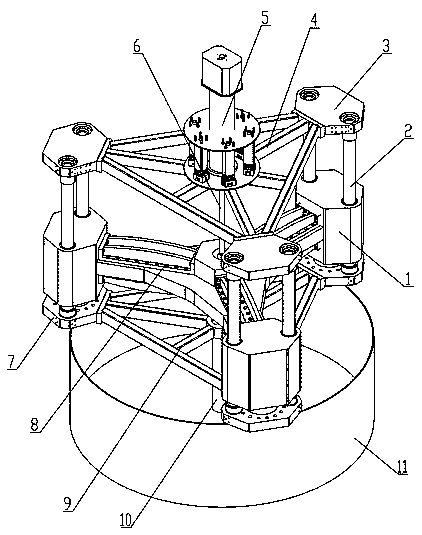
[0028] like image 3 , Figure 4 The difference between the split type hydraulic piling hammer shown in this embodiment and the above embodiment (Embodiment 1) is that there is no guide rod sliding sleeve 12 on the lower support frame 9, so there is no Set the center guide rod 10. There are only six guide structures formed by the column guide rods on the rigid body formed by the tup 1 and the tup connecting frame 8 .

Embodiment 3

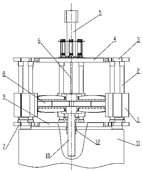
[0030] like Figure 5 , Image 6 The split-type hydraulic piling hammer shown includes three hammer heads 1, which are located on the circumference of the cylinder wall of the circular tubular foundation pile 11, and the three hammer heads 1 are equidistant along the circumference of the cylinder wall. Interval settings. The three hammerheads 1 are respectively fixedly installed on the arm ends of the three outrigger arms of the hammerhead connecting frame 8, so that the three hammerheads 1 and the hammerhead connecting frame 8 form a rigid body. A hydraulic cylinder 5 is fixedly installed on the upper support frame 4 , and several energy accumulators are also arranged around the hydraulic cylinder 5 , and the energy accumulators are all fixedly installed on the upper support frame 4 . Each extended end of the upper supporting frame 4 is fixedly installed with a column 2 respectively. The upper end of the column 2 is fixedly connected with the upper supporting frame 4 throu...

Embodiment 4

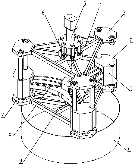
[0035] like Figure 7 , Figure 8 The difference between the split type hydraulic piling hammer shown in this embodiment and the above embodiment (Embodiment 3) is that there is no guide rod sliding sleeve 12 installed on the lower support frame 9, so there is no Set the center guide rod 10. The rigid body formed by the tup 1 and the tup connecting frame 8 has only three guide structures formed by the column guide rods.


PUM


Abstract

The invention discloses a split type hydraulic pile hammer which comprises at least two hammerheads. The hammerheads are fixedly connected to a hammerhead connecting frame, a hydraulic cylinder pistonrod fixedly installed on an upper bearing frame is connected with the hammerhead connecting frame, and the center line of the hydraulic cylinder passes through the mass center of a rigid body composed of the hammerheads and the hammerhead connecting frame; the upper bearing frame is fixedly connected with a lower bearing frame through a stand column. A stand column is a sliding guiding rod slidably penetrating through the hammerheads or a sliding guiding rod slidably arranged in a sliding groove. A guiding rod sliding sleeve is fixedly connected to the lower bearing frame, a center guiding rod is fixedly connected to the hammerhead connecting frame, and the center guiding rod is slidably supported into the guiding rod sliding sleeve; the center lines of the center guiding rod and the hydraulic cylinder are located on the same straight line. The split type hydraulic pile hammer has the large enough impact energy, a large-caliber pipe pile can be directly hammered to a force holding layer, the hammering efficiency is high, and the impact energy loss is small.

Description

technical field [0001] The invention relates to a pile machine used for engineering foundation construction, in particular to a hydraulic pile driving hammer capable of realizing large-diameter foundation pile sinking construction. Background technique [0002] Pile foundation is a form of construction engineering foundation widely used in sea and land, especially with the increasing development and progress of my country's engineering construction, in recent years, my country's ocean engineering, offshore wind power, reclamation and island construction, large bridges, etc. Great progress, these projects not only have very high engineering coefficients, but also become more and more difficult to construct pile foundations, and the length and diameter of foundation piles are also becoming larger and larger, which requires the use of The piling machinery in the formation has higher striking energy and higher striking frequency. At present, the steel circular tubular foundation ...

Claims


Application Information

Patent Timeline
Patent Type & Authority Applications(China)
IPC IPC(8): E02D7/10E02D7/16
CPCE02D7/10E02D7/16
Inventor 许清王玉立施光林张静孟春明冯启阳王小娟许向华
Owner JIANGSU JUWEI MACHINERY
Why Eureka
Try Eureka