Construction method of super-deep shield shaft in water-rich weak stratum

A technology for weak strata and construction methods, applied in vertical shaft equipment, earthwork drilling, wellbore lining, etc., can solve problems such as inapplicability, reduced construction efficiency, and major safety issues, and achieve improved construction efficiency, good stability, The effect of improving construction safety

Active Publication Date: 2019-04-16
中铁隧道集团二处有限公司
View PDF6 Cites 6 Cited by
  • Summary
  • Abstract
  • Description
  • Claims
  • Application Information

AI Technical Summary

Problems solved by technology

[0014] 1. Using custom-made rectangular concrete-filled steel tube components and fittings for assembly operations will produce rectangular concrete-filled steel tube components and fittings that cannot be assembled on site due to on-site construction errors, reducing construction efficiency;
[0015] 2. Use micro-expansion concrete to fill the space between the concrete-filled steel pipe purlin and the inner wall of the shield shaft, so that the combination between the steel pipe concrete purlin and the inner wall of the shield shaft is not strong enough
[0016] 3. This technology is only suitable for relatively shallow shield shafts with good geological conditions (such as shafts with a depth of no more than 30m), but for ultra-deep shafts with a depth of more than 40m in soft strata rich in water and with confined water , this technology has major security problems and is not applicable

Method used


Image

  • Construction method of super-deep shield shaft in water-rich weak stratum
  • Construction method of super-deep shield shaft in water-rich weak stratum
  • Construction method of super-deep shield shaft in water-rich weak stratum

Examples


Embodiment

[0060] A construction method for an ultra-deep shield shaft in a water-rich and weak stratum, comprising the following steps:

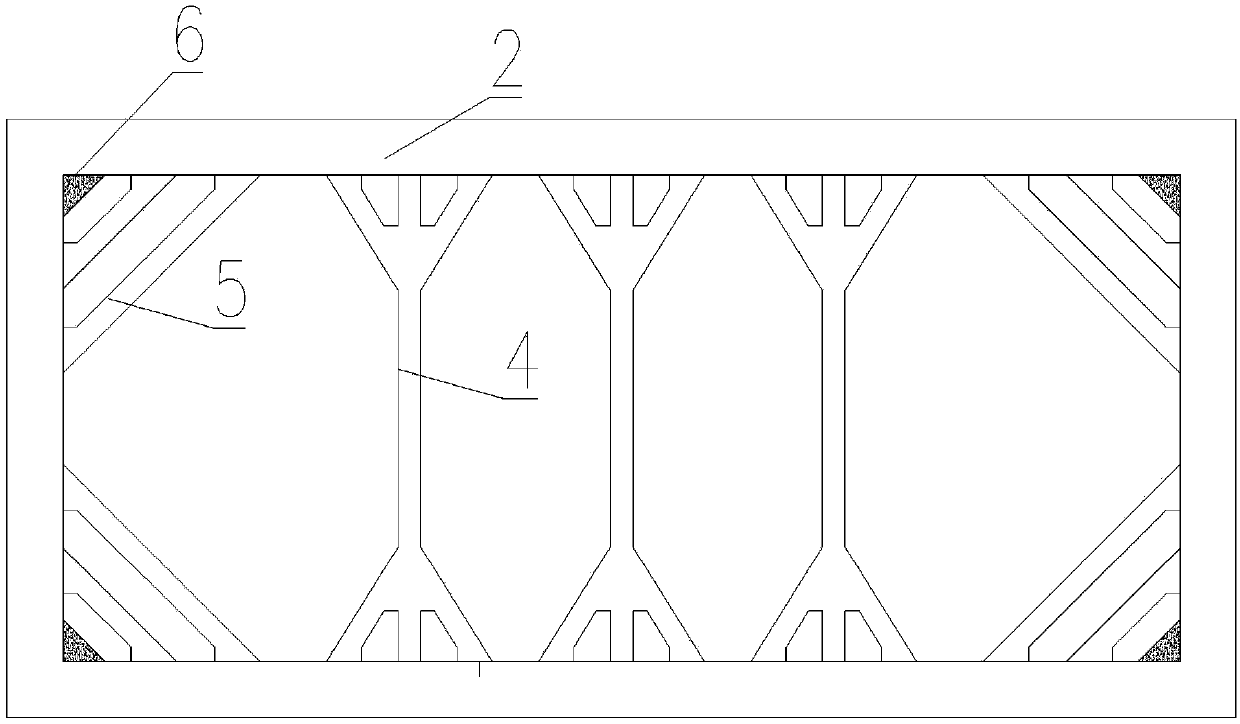
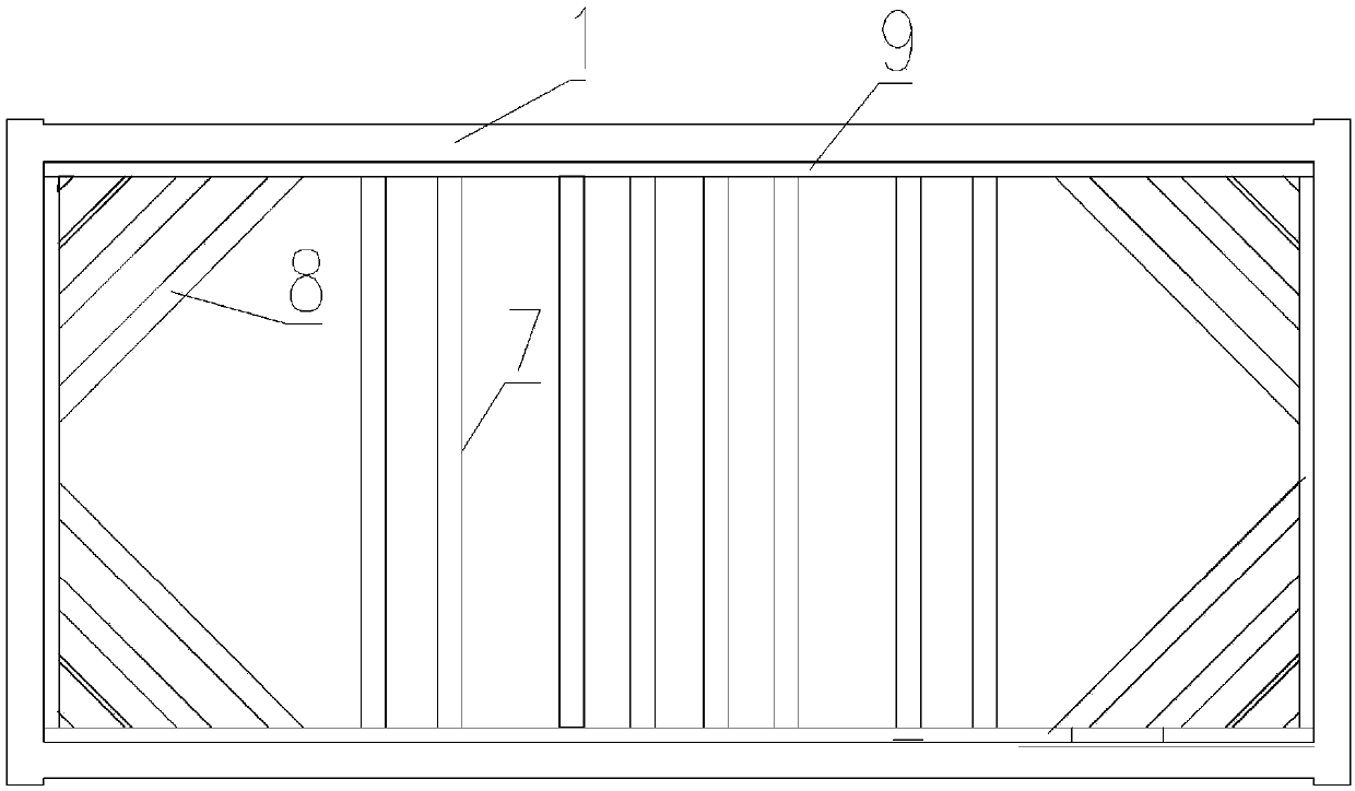
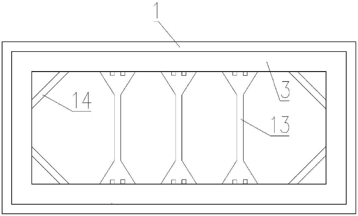
[0061] Step 1: Construct the enclosure structure of the underground diaphragm wall 1 of the shaft;

[0062] Step 1.1: First construct the double-span I-beam joint of the underground diaphragm wall 1;

[0063] Step 1.2: Divide the trough into troughs, check the verticality of the trough wall, hoist the reinforcement cage, and finally pour the underwater concrete;

[0064] Step 1.3: Install fiberglass reinforcement cages in the scope of the starting portal or receiving portal of the shield machine, and pour underwater concrete;

[0065] Step 1.4: complete the construction of all underground diaphragm wall 1 structures in turn;

[0066] Step 2: Stratum reinforcement at the end of the shield shaft;

[0067] Step 3: Divide the upper 20 meters of the shaft into four layers, carry out excavation layer by layer, and erect the steel support system;

[0068...


PUM

PropertyMeasurementUnit
Diameteraaaaaaaaaa
Thicknessaaaaaaaaaa

Abstract

The invention discloses a construction method of a shield shaft. The method comprises the following steps that 1, an underground continuous wall enclosure structure of the shaft is constructed; 2, thestratum at the end of the shield shaft is reinforced; 3, the upper 20-m portion of the shaft is divided into four layers, and excavation and erection of a steel bracing support system are conducted layer by layer; 4, the lower portion of the shaft is divided into five layers, and the fifth layer to the ninth layer of the shaft are excavated separately; 5, the pit bottom of the shaft is treated, pile head concrete of an uplift pile is broken and removed at first, then the bottom is manually cleaned, base cushioning and water proofing construction is carried out, finally, bottom plate steel ribs are tied, and concrete is poured; 6, a shaft support is disassembled, and side walls and columns are constructed. The construction method of the shield shaft has the advantages that through construction methods of vertical layering, construction from top to bottom and support at first and afterwards excavation, the construction efficiency of the shield shaft is effectively improved; by setting the steps of reinforcing a shield receiving end, the shield receiving end is effectively protected against damage in the construction process of the shaft.

Description

technical field [0001] The invention relates to the technical field of shield shaft excavation and lining construction, in particular to a construction method for an ultra-deep shield shaft in a water-rich and soft stratum. Background technique [0002] The shield shaft is a well-shaped structure in which the shield device is lowered into the shield device for starting or the shield machine is lifted out of the shield machine during the shield tunneling method construction process. At present, with the popularization of the application of the shield machine, more and more applications are made to the shield shaft. [0003] For example, the patent document of Chinese invention patent application number 201310480442.6 discloses a construction method of a shield shaft assembly type concrete filled steel tube inner support system, the steps are as follows: [0004] The first step is the factory manufacturing of rectangular concrete-filled steel tube components: in the factory, ...

Claims


Application Information

Patent Timeline
IPC IPC(8): E21D5/11E21D7/00
CPCE21D5/11E21D7/00
Inventor 许维青翟志国姚杰唐伟李义华王乐明古艳旗苏清贵李强邢会冲何博杨振朋邓业华张华莫松王轩杨志永刘涛
Owner 中铁隧道集团二处有限公司
Why Eureka
Try Eureka