
A latent heat recovery water heater

A water heater and latent heat technology, applied in water heaters, fluid heaters, lighting and heating equipment, etc., can solve the problems of no latent heat recovery, environmental pollution, inconvenient disassembly and assembly, etc.

Active Publication Date: 2021-06-08
SIYUAN ELECTRIC APPLIANCES
View PDF0 Cites 0 Cited by
  • Summary
  • Abstract
  • Description
  • Claims
  • Application Information

AI Technical Summary

Problems solved by technology

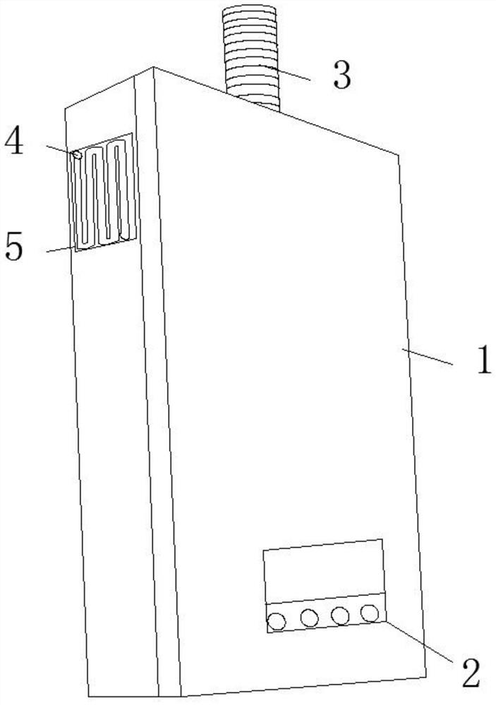
[0004] The object of the present invention is to provide a latent heat recovery type water heater to solve the problem that the existing water heaters proposed in the above background technology do not have a good latent heat recovery function, and there is still a large amount of latent heat in the process of combustion heating. into the atmosphere, resulting in environmental pollution and low energy utilization. At the same time, the existing water heater connection structure is relatively compact, generally one-piece structure, which is inconvenient to disassemble and assemble, resulting in low maintenance efficiency.

Method used


Image

  • A latent heat recovery water heater
  • A latent heat recovery water heater

Examples


Embodiment 1

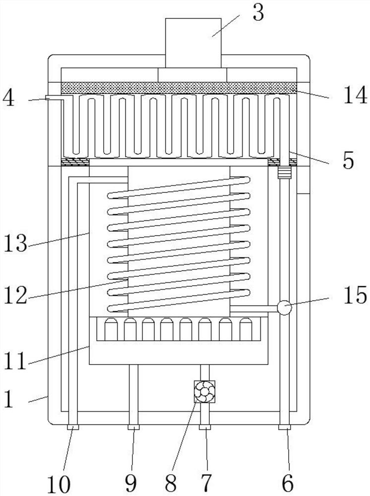
[0021] see Figure 1-2 , this embodiment provides a latent heat recovery type water heater, including a water heater shell 1, a microcomputer main controller 2 is embedded in one side of the water heater shell 1, a smoke exhaust pipe 3 is installed on the top of the water heater shell 1, and the water heater shell A second heat exchanger 5 is embedded on the side of the body 1 close to the exhaust pipe 3, a second heat exchanger water outlet 4 is arranged on one side of the second heat exchanger 5, and a second heat exchanger 5 is installed on the top of the second heat exchanger 5. The choke plate 14, the bottom of the smoke exhaust pipe 3 is provided with a filter inner core, the top of the choke plate 14 is provided with a return air cavity, the filter core is embedded in the return air cavity, and the bottom of the second heat exchanger 5 is provided with a combustion chamber. Chamber 13, the bottom of the second heat exchanger 5 is equipped with a thermal insulation board...

Embodiment 2

[0024] see Figure 1-2 , on the basis of Embodiment 1, a further improvement has been made: the interior of the burner 11 is provided with a plurality of flame nozzles, which accelerates the combustion efficiency and improves the instant hot water supply performance of the water heater, the water inlet 6, the air inlet 7, the gas One side of the inlet 9 and the hot water outlet 10 is provided with a mounting screw sleeve, threaded connection, stable connection, convenient installation, and the inside of the mounting screw sleeve is provided with a sealing gasket, which is sealed and protected, ensuring the stability of the material dredging process. Avoid leakage.

[0025]Wherein, the four corners of the water heater housing 1 are equipped with anti-collision foot pads, and the four corners are anti-collision protection. When the outer four corners are hit, the buffer performance can be improved to prevent the internal components from being damaged. The second heat exchanger 5...


PUM


Abstract

The invention discloses a latent heat recovery type water heater, which comprises a water heater shell, a microcomputer main controller is embedded and installed on one side of the water heater shell, a smoke exhaust pipe is installed on the top of the water heater shell, and the water heater shell A second heat exchanger is embedded and installed near the side of the exhaust pipe, a second heat exchanger water outlet is provided on one side of the second heat exchanger, and a wind baffle is installed on the top of the second heat exchanger , the bottom of the second heat exchanger is provided with a combustion chamber. The present invention solves the problem that the existing water heater does not have a good latent heat recovery function, and the waste gas with a large amount of latent heat in the combustion heating process is discharged and discharged to the atmosphere. Among them, the problems of environmental pollution and low energy utilization rate are caused. At the same time, the connection structure of the existing water heater is relatively compact, and it is generally a one-piece structure. It is inconvenient to disassemble and assemble, resulting in the problem of low maintenance efficiency.

Description

technical field [0001] The invention relates to the technical field of water heaters, in particular to a latent heat recovery type water heater. Background technique [0002] Latent heat is the heat absorbed or released when a substance undergoes a phase change (change of state of matter) when the temperature does not change. When a substance changes from low energy to high energy, it absorbs latent heat, and vice versa, it releases latent heat. For example, when a liquid boils, part of the latent heat absorbed is used To overcome the intermolecular attraction, the other part is used to do work against the atmospheric pressure during the expansion process. The heat of fusion, heat of vaporization and heat of sublimation are all latent heat. Expressed as heat absorbed or released. [0003] During the working process of the water heater, the existing water heater does not have a good latent heat recovery function, and there is still a large amount of latent heat exhaust gas d...

Claims


Application Information

Patent Timeline
Patent Type & Authority Patents(China)
IPC IPC(8): F24H1/14F24H1/16F24H9/00F24H9/14F24H9/18F24H9/20F23J15/02
CPCF23J15/025F24H1/145F24H1/165F24H9/0005F24H9/146F24H9/1836F24H9/2035
Inventor 徐宁向熹
Owner SIYUAN ELECTRIC APPLIANCES
Learn More