Random modulation and demodulation method for restraining cross coupling of optical fiber gyroscope

A fiber optic gyroscope and cross-coupling technology, applied in Sagnac effect gyroscopes and other directions, can solve the problems of lengthened closed-loop response of gyroscopes, decreased dynamic performance, and long demodulation period, so as to reduce random walks and improve dynamic performance. , to achieve the effect of de-correlation

Active Publication Date: 2019-04-16
XIAN AEROSPACE PRECISION ELECTROMECHANICAL INST
View PDF11 Cites 6 Cited by
  • Summary
  • Abstract
  • Description
  • Claims
  • Application Information

AI Technical Summary

Problems solved by technology

At the same time, it is pointed out in the article that in a demodulation cycle, the number of positive and negative signs of the demodulated signal must be equal, but due to the randomness of the modulation sequence, the demodulation cycle of the gyro will be very long (about one second) and not fixed, which means It will lead to longer closed-loop response of gyroscope and lower dynamic performance

Method used


Image

  • Random modulation and demodulation method for restraining cross coupling of optical fiber gyroscope
  • Random modulation and demodulation method for restraining cross coupling of optical fiber gyroscope
  • Random modulation and demodulation method for restraining cross coupling of optical fiber gyroscope

Examples


Embodiment Construction

[0033] The present invention will be described in further detail below in conjunction with the accompanying drawings and specific embodiments.

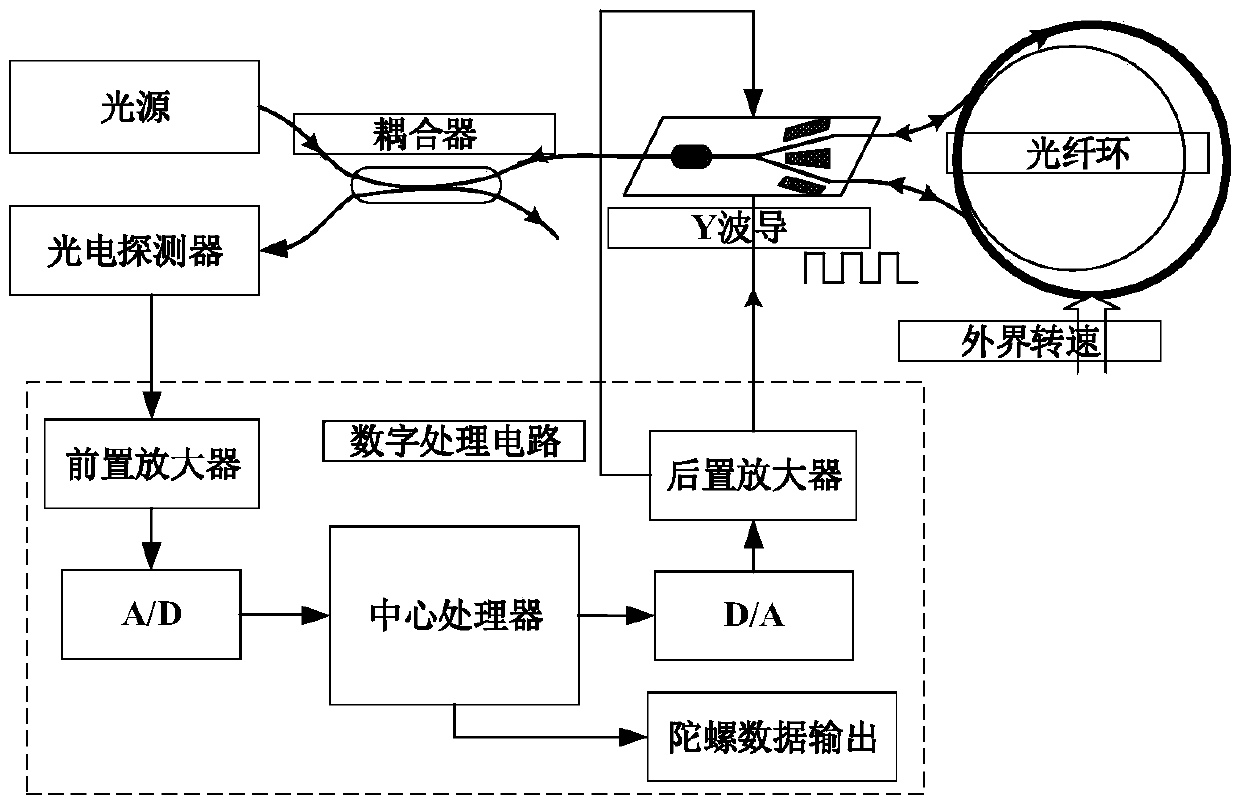
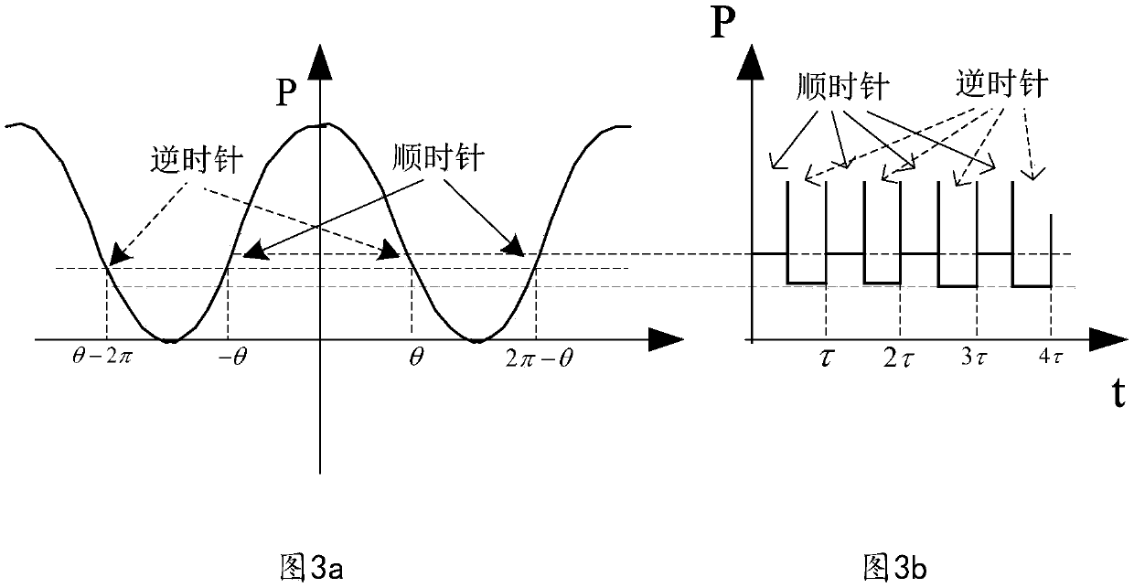
[0034] In the present invention, by generating random or pseudo-random modulation phase and applying it to the Y waveguide, the photodetector detects the modulated voltage signal in real time and obtains the rotational speed error and 2π reset error according to the demodulation sequence, which are used as the feedback signal of the gyro closed loop to realize the gyro closed-loop control.

[0035] The specific modulation and demodulation is realized through the following process:

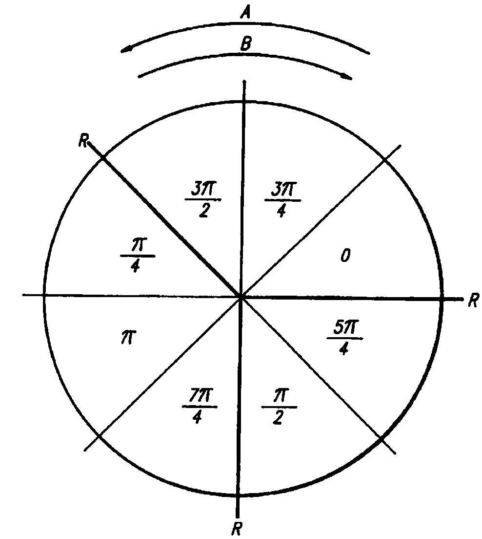
[0036] 1. Gyro modulation phase graph structure:

[0037] In order to achieve the best detection sensitivity of the gyroscope, according to the size of different gyroscope fiber rings and the optical power of the light source, select the appropriate bias value operating point of the gyroscope to achieve the best signal-to-noise ratio. Usually the bias val...


PUM


Abstract

The invention discloses a random modulation and demodulation method for restraining cross coupling of an optical fiber gyroscope. A random or pseudo-random sequence is used for generating two sets ofopposite mirror image modulation sequences, and the two modulation sequences which are mirror images are combined to form a final modulation sequence; the optical phase of the gyroscope is modulated;and finally, a digital center processor performs demodulation processing on the voltage value received by a photoelectric detector according to the corresponding demodulation sequence, the rotating speed error of the gyroscope is obtained, and the error signal serves as a feedback signal of a closed loop, so that closed-loop control of the gyroscope is realized. According to the method, the modulation sequence is generated by adopting a random number, the correlation of modulation and demodulation on statistics is realized, and the cross coupling between modulation signals and demodulation signals in the optical fiber gyroscope is inhibited. Meanwhile, the method can achieve demodulation within any integer multiple optical fiber ring transit time, the response of the gyroscope closed-loopis accelerated, and the dynamic performance of a system is improved.

Description

technical field [0001] The invention relates to a modulation and demodulation method of an interference-type digital closed-loop fiber optic gyroscope, in particular to a random modulation and demodulation method for suppressing cross-coupling of the fiber optic gyroscope. technical background [0002] Digital closed-loop fiber optic gyroscope is an instrument for measuring angular velocity. It is widely used in inertial systems such as navigation and positioning. It mainly includes light source, coupler, Y waveguide, fiber optic ring, photodetector, and digital processing circuit. [0003] The basic principle is that the light emitted by the light source is divided into two beams of forward and reverse propagation light waves through the Y waveguide, and the digital processing circuit applies a modulation signal at the Y waveguide to perform phase modulation on the light waves. Converted into an electrical signal, the central processor samples and demodulates the electrical...

Claims


Application Information

Patent Timeline
Patent Type & Authority Applications(China)
IPC IPC(8): G01C19/72
CPCG01C19/72
Inventor 黄博潘子军吉世涛洪伟杨鹏汪刚娄少峰曹平平
Owner XIAN AEROSPACE PRECISION ELECTROMECHANICAL INST
Why Eureka
Try Eureka