Wind measuring device and method based on multiple transmitting and receiving ultrasonic sensors

A multi-transmitting, multi-receiving and receiving sensor technology, applied in measurement devices, instruments, fluid velocity measurement, etc., can solve problems such as high maintenance costs, corrosion, and limited range of wind speed measurement

Active Publication Date: 2019-04-16
JILIN UNIV
View PDF16 Cites 9 Cited by
  • Summary
  • Abstract
  • Description
  • Claims
  • Application Information

AI Technical Summary

Problems solved by technology

The precise measurement of wind speed and direction plays an important role in meteorology, aviation, navigation, military and other fields. The use of human anemometers mainly includes mechanical anemometers, thermal anemometers and ultrasonic anemometers. Mechanical anemometers mainly include wing-shaped anemometers and cup-shaped anemometers, but due to the internal

Method used


Image

  • Wind measuring device and method based on multiple transmitting and receiving ultrasonic sensors
  • Wind measuring device and method based on multiple transmitting and receiving ultrasonic sensors
  • Wind measuring device and method based on multiple transmitting and receiving ultrasonic sensors

Examples


Embodiment 1

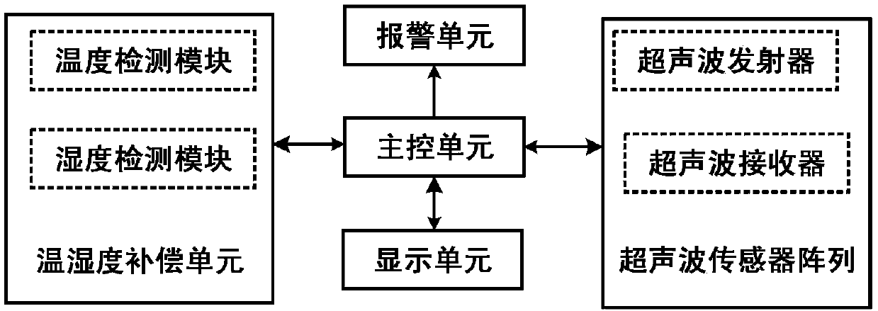
[0097] Such as figure 1 As shown, the wind measuring device based on multi-send and multi-receive ultrasonic sensors is characterized in that it includes: an ultrasonic sensor array, a main control unit, a temperature and humidity compensation unit, an alarm unit and a display unit; wherein the ultrasonic sensor array, the temperature and humidity compensation unit, and the alarm Both the unit and the display unit are connected to the main control unit. The temperature and humidity compensation unit detects the temperature and humidity in the external environment and sends the detected value to the main control unit to achieve the purpose of calibrating the ultrasonic propagation speed. At the same time, the main control unit keeps observing whether the temperature and humidity compensation unit is working normally. If the temperature and humidity compensation unit fails, the main control unit controls the alarm unit to send an alarm signal about the failure of the temperature...

Embodiment 2

[0149] In order to verify the feasibility of the method provided by the present invention, a simulation experiment for verifying the feasibility is designed, and the simulation experiment is carried out on MATLAB software. The simulation experiment conditions are as follows: the frequency of the ultrasonic signal emitted by the simulated transmitting array element is 40kHz, and the noise received by the receiving array element is additive white Gaussian noise. The wind speed scanning range is 0~60m / s, and the step size is 0.1m / s. The scanning range of wind direction angle is 0°~359°, the step size is 1°, and the number of snapshots is 5000. When the signal-to-noise ratio SNR=10dB, the following three sets of random wind speed and direction parameters are respectively estimated:

[0150] The first set of parameters: V=5.1m / s; θ=45°

[0151] The second set of parameters: V=21.3m / s; θ=135°

[0152] The third set of parameters: V=51.7m / s; θ=315°

[0153] Figure 4A and Figur...


PUM


Abstract

The invention belongs to the technical field of wind speed and direction measurement, and particularly relates to a wind measuring device and method based on multiple transmitting and receiving ultrasonic sensors. The device comprises an ultrasonic sensor array, a main control unit, a temperature and humidity compensation unit, an alarm unit and a display unit. According to the invention, two ultrasonic sensor subarrays composed of two ultrasonic transmitting sensors which transmit ultrasonic signals and six ultrasonic receiving sensors which receive ultrasonic signals are used to receive ultrasonic array data containing wind speed and direction information; then the array data information received by two ultrasonic sensor subarrays are merged, and the wind speed and direction informationis measured through a beamforming algorithm; different subarray flow vectors formed by two ultrasonic sensor subarrays contain more wind parameter information than an array flow vector or array flow vectors composed of two same subarray flow vectors; and the wind speed and direction measurement accuracy is higher.

Description

technical field [0001] The invention belongs to the technical field of wind speed and direction measurement, and in particular relates to a planar ultrasonic wind speed and direction measurement device and method with multiple transmissions and multiple receptions. Background technique [0002] Wind is a common natural phenomenon and also an important renewable and recyclable clean energy. The precise measurement of wind speed and direction plays an important role in meteorology, aviation, navigation, military and other fields. The use of human anemometers mainly includes mechanical anemometers, thermal anemometers and ultrasonic anemometers. Mechanical anemometers mainly include wing-shaped anemometers and cup-shaped anemometers, but due to the internal rotating parts, they are easily worn or corroded, resulting in reduced measurement accuracy and high maintenance costs. The thermal anemometer mainly uses a thermal probe to measure the wind speed by measuring the cooling r...

Claims


Application Information

Patent Timeline
IPC IPC(8): G01P5/24G01P13/02
CPCG01P5/245G01P13/02Y02A90/10
Inventor 李新波朱阁彦孙子凤贾云龙李厚禹刘亚周刘帅于润泽
Owner JILIN UNIV
Why Eureka
Try Eureka