Bus passenger flow monitoring system and working method thereof

A monitoring system and bus technology, applied in the field of buses, can solve the problems that it is difficult to judge whether passengers get on or get off the bus, restricts wide application, and has high computational complexity, and achieves intelligent proximity sensing, strong penetrating power, small size effect

Inactive Publication Date: 2019-04-16
ANHUI ANKAI AUTOMOBILE
View PDF3 Cites 5 Cited by
  • Summary
  • Abstract
  • Description
  • Claims
  • Application Information

AI Technical Summary

Problems solved by technology

At present, the system applied to bus passenger flow monitoring is mainly realized by infrared technology or binocular video technology. Infrared technology uses infrared sensors installed on the upper part of the front and middle doors of buses. The light emitted back from the passenger recognizes the movement of the passenger. The disadvantage is that when many people get on and off the bus at the same time, the recognition rate is not high, and it is difficult to judge whether the passenger is going to get on or get off the car. Therefore, the infrared technology detection system is used. has certain limitations
[0004] The use of binocular video technology is to use binocular cameras, based on binocular stereo vision technology, using the principle of parallax and using imaging equipment to obtain two images of the measured object from different positions, and by calculating the position deviation between the corresponding points of the image to obtain The information of the measured object has high recognition accuracy. Because the binocular camera technology is very sensitive to ambient light, when the lighting angle and light intensity of the application scene change (night, backlight), the recognition effect drops sharply, and the camera baseline is also limited. Its measurement range is limited. This method is a purely visual method, which requires pixel-by-pixel calculation and matching. The calculation complexity is high, and the overall hardware cost is high, which limits its wide application.

Method used


Image

  • Bus passenger flow monitoring system and working method thereof
  • Bus passenger flow monitoring system and working method thereof
  • Bus passenger flow monitoring system and working method thereof

Examples


Embodiment Construction

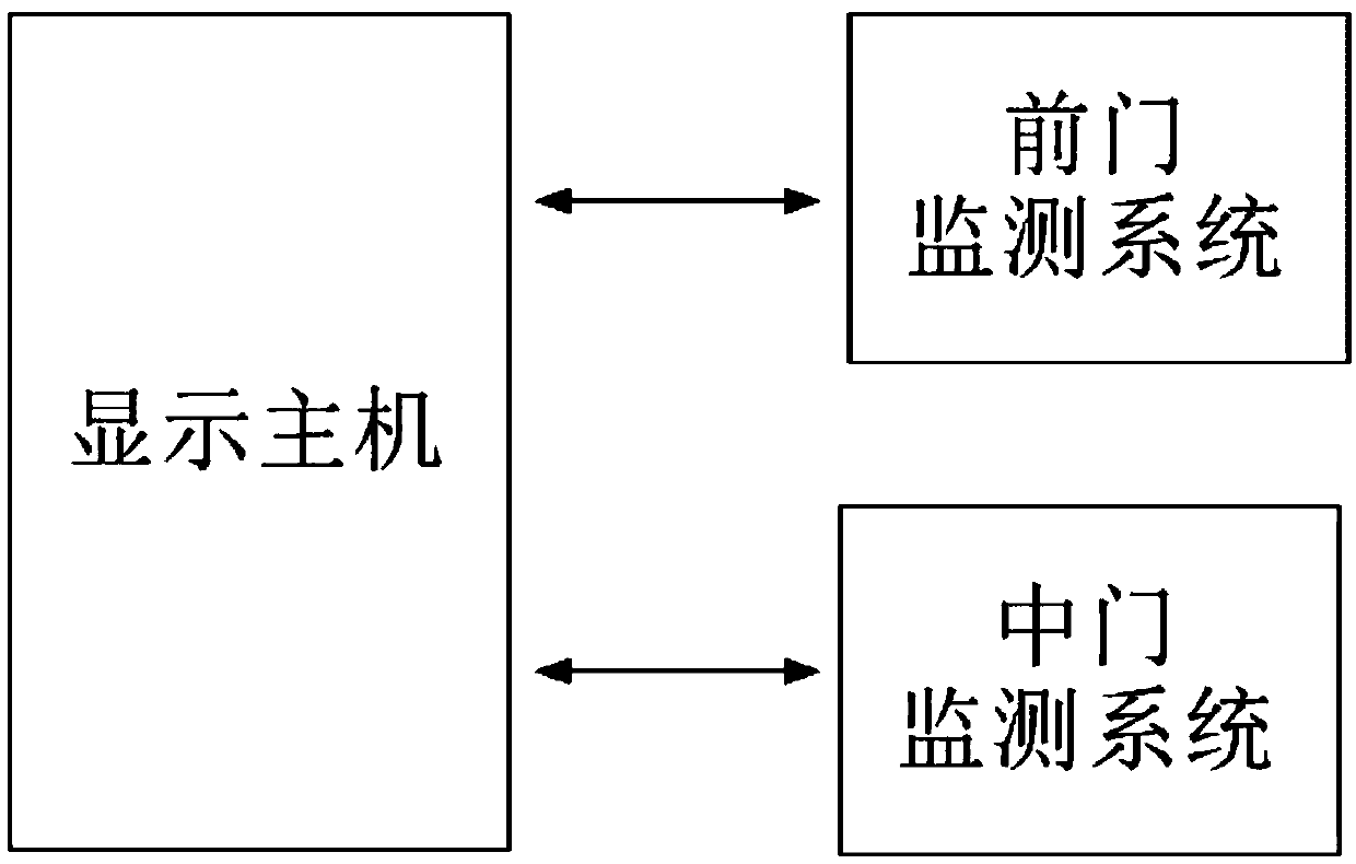
[0040] As attached figure 1 As shown, the present invention is a bus passenger flow monitoring system, which includes a front door monitoring system, a middle door monitoring system, and a display host, all of which form a passenger flow monitoring network through a CAN network. The display host is installed on the dashboard of the cab. The front door monitoring system and the middle door monitoring system are hidden and installed on the inside of the protective plate on the upper part of the front door and the middle door of the carriage. The work of the front door monitoring system and the middle door monitoring system are controlled by the display host. The display host receives the door opening or closing signal and sends the corresponding CAN command through the CAN bus. When the front door and the middle door are opened, the front door monitoring system and the middle door monitoring system start to work, otherwise, the front door monitoring system and the middle door moni...


PUM


Abstract

The invention discloses a bus passenger flow monitoring system. The system comprises a front door monitoring system, a middle door monitoring system and a display main machine, wherein the front doormonitoring system, the middle door monitoring system and the display main machine form a passenger flow monitoring network through a CAN network. When a bus stops at a bus stop and a bus door is opened, the display main machine judges the opening and closing of the bus door through a door control signal, the door control signal is sent to the front door monitoring system and the middle door monitoring system through a CAN communication interface, after central processors in the front door monitoring system and the middle door monitoring system receive the door control signal, a control circuitis connected to turn on the power supply for a radar sensor, the radar sensor is used for measuring the distance of a static or moving object, the moving direction and the displacement speed, the type of the moving object is distinguished, and statistics is carried out as well; and when the bus door is closed, the door control monitoring unit receives a door closing signal, the power supply of the radar sensor is turned off, the statistics of the collected signals are finished, the statistics result is sent to the display main machine through the CAN bus, and the display main machine receivesthe CAN information.

Description

Technical field [0001] The invention belongs to the field of buses, and relates to a passenger flow monitoring technology, in particular to a bus passenger flow monitoring system and a working method thereof. Background technique [0002] The increasingly sophisticated and huge urban public transport system has brought convenience and speed to the travel of the majority of passengers, but at the same time, in terms of management and effective monitoring, it has brought great internal management pressure and social pressure to public transportation companies and traffic management departments. Especially in the operation and dispatch of vehicles during holidays or rush hours, the traffic management department needs to effectively understand the vehicle location and passenger flow information of each station and each operating line, coordinate shifts, timely supplement operating vehicles, and relieve traffic pressure. [0003] This requires the collection system to collect statistics...

Claims


Application Information

Patent Timeline
Patent Type & Authority Applications(China)
IPC IPC(8): G01V8/00G01V8/10G07C9/00
CPCG01V8/005G01V8/10G07C9/00
Inventor 吴成加林红宇赵圣宝
Owner ANHUI ANKAI AUTOMOBILE
Why Eureka
Try Eureka