

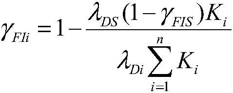
Fault isolation rate distribution method
A technology of fault isolation rate and allocation method, applied in the field of fault detection rate allocation, it can solve the problems that affect the test design results, the allocation results are very different, and the two skins are easy to understand, the allocation results are reasonable, and the algorithm is simple. Effect
- Summary
- Abstract
- Description
- Claims
- Application Information
AI Technical Summary
Problems solved by technology
Method used
Image

Examples
Embodiment Construction
[0041] Take a system as an example, the system contains 5 sub-systems, the fault detection rate is 90%, and the fault isolation rate is 90%. Find the assigned value of the fault isolation rate of each sub-system.
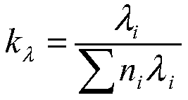
[0042] According to the system reliability distribution results, the mean time between failures (MFHBF) of each system can be obtained, and the reciprocal of MPHBF is the failure rate of each system, as shown in Table 1.
[0043] Table 1 Reliability distribution results
[0044] Serial number
name
Mean time between failures (hours)
λ i
1
Subsystem 1
160
0.00625
2
Subsystem 2
80
0.0125
3
Subsystem 3
700
0.001429
4
Subsystem 4
300
0.003333
5
Subsystem 5
280
0.003571
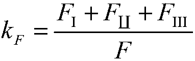
[0045] According to the failure mode and impact analysis results, the number of failure modes shown in Table 2 is obtained.
[0046] Table 2 Results of failure modes
[0047]
[0048]
[0049] According to the maintainability index distribution, the maintainability distribution results shown in Table 3 are obt...
PUM
 Abstract
Description
Claims
Application Information