Quantum magnetic pole transmission power generation device and control method thereof
A technology of power generation device and control method, which is applied in the direction of electromechanical devices, mechanical energy control, electrical components, etc., can solve the problems of not being able to give full play to the advantages, large magnetic damping, etc., and achieve the effects of obvious power generation gain, easy structure, and obvious effect
- Summary
- Abstract
- Description
- Claims
- Application Information
AI Technical Summary
Problems solved by technology
Method used
Image

Examples
Embodiment 1
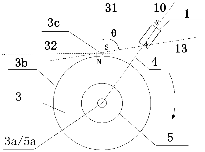
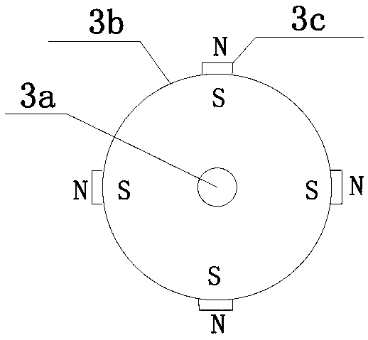
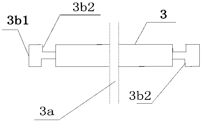
[0068] A power generation device for quantum magnetic pole transmission, including a rotary generator 5, a starting device 6, a magnetic moment turntable 3, a logic power supply 2 and a set of electromagnetic device 1, and its partial structure is schematically shown as figure 1 Shown; The structure of the magnetic moment turntable is shown in Figure 2a As shown, the disk body material is made of non-magnetic alloy. The disk has a rotating shaft 3a, a radius of 100cm, and a thickness of 10cm. Around the outer peripheral surface 3b, four permanent magnets 3c with an area of 10×6cm and a thickness of 1.5cm are arranged. The permanent magnets are evenly spaced between each other. Arrangement, the S pole faces the rotating shaft, the N pole faces the outer edge, the magnetic pole connection line 11 coincides with the axis 12 of the magnetic moment turntable 3; the rotating shaft 5a of the generator is transmitted through the mechanical transmission device and the rotating shaft ...
Embodiment 2
[0079] In the above embodiment 1, the function of the electromagnetic device 1 is to double as the magnetoelectric signal sensor of the relative position of the quantum magnetic pole generating device and the permanent magnet 3c. Since the main function of the coil 1a is to generate the quantum magnetic pole, the winding has a current overload capability requirement, and the magnetic The function of the electrical signal sensor is to generate magnetoelectric signals, and the number of winding turns is related to the signal sensitivity of magnetoelectric induction, which will be limited by the design of the electromagnetic force coil as the magnetoelectric induction coil.
[0080] In this embodiment, the magnetoelectric induction coil and the electromagnetic force coil are designed separately, and the coil 1a surrounding the magnetic core 1b is designed into two groups, one group is the electromagnetic force coil, which is designed according to the requirements for the current ov...
Embodiment 3
[0083] In embodiment 1 and embodiment 2, the position sensing function of permanent magnet 3c is realized by the coil of electromagnetic device, and the signal sensitivity of magnetoelectric induction is not as good as special-purpose signal sensor; On the basis of embodiment 1 and embodiment 2, In this embodiment, the electromagnetic device 1 produces quantum magnetic poles and serves as a function discrete design of the signal sensor, adopts 4 special magnetoelectric modules as the signal sensor, and the 4 special magnetoelectric modules are respectively fixedly installed adjacent to the peripheral surface 3b of the magnetic moment turntable 1. The parts close to the rotation circumference of the permanent magnet 3c are evenly arranged alternately.
[0084] In this embodiment, four dedicated signal sensors are used, and the sensitivity of the position sensing signal of the permanent magnet 3c is higher.
[0085] The starting device 6 of the foregoing embodiment can also be t...
PUM
 Abstract
Description
Claims
Application Information
 - R&D
- Intellectual Property
- Life Sciences
- Materials
- Tech Scout
- Unparalleled Data Quality
- Higher Quality Content
- 60% Fewer Hallucinations
Browse by: Latest US Patents, China's latest patents, Technical Efficacy Thesaurus, Application Domain, Technology Topic, Popular Technical Reports.
© 2025 PatSnap. All rights reserved.Legal|Privacy policy|Modern Slavery Act Transparency Statement|Sitemap|About US| Contact US: help@patsnap.com