Method for increasing molten steel circulating flow quantity in RH refining process

A refining process and circulating flow technology, which is applied in the field of molten steel refining technology, can solve the problems of shortening RH refining time and difficulty in circulating flow, and achieve the effects of improving RH decarburization efficiency, increasing circulating flow, and prolonging the time of lifting action

Active Publication Date: 2019-04-19
CENT IRON & STEEL RES INST
View PDF5 Cites 6 Cited by
  • Summary
  • Abstract
  • Description
  • Claims
  • Application Information

AI Technical Summary

Problems solved by technology

It solves the problem that it is difficult to further increase the circulation flow in refining without changing the existing RH dipping tube and other devices. It also plays an important role in the production of high-quality clean steel by improving product quality and increasing the economic benefits of iron and steel enterprises. The reference and guiding significance of
At the same time, the method is simple and reliable, has strong operability, and is easy to implement. It can significantly increase the circulation flow in the RH smelting process, improve the RH decarburization efficiency, greatly shorten the RH refining time, and have a high level of cleanliness of molten steel. It is a good solution without changing the It is difficult to further increase the circulating flow rate in the refining of existing RH dipping tubes and other devices, improve product quality and increase the economic benefits of iron and steel enterprises

Method used


Image

  • Method for increasing molten steel circulating flow quantity in RH refining process
  • Method for increasing molten steel circulating flow quantity in RH refining process
  • Method for increasing molten steel circulating flow quantity in RH refining process

Examples


Embodiment 1

[0024] For the production of ultra-low carbon IF steel in a converter-RH-CC process flow, this method is used for RH refining process. The specific implementation process is as follows:

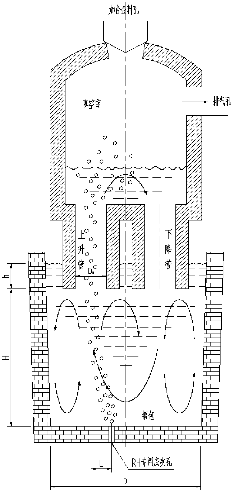
[0025] (1) After the converter smelting is completed and the ladle enters the RH refining station, connect the blowing pipe to the pre-set ladle bottom blowing hole for the circulation flow of the RH refining process, and connect the ladle bottom argon blowing system for use;

[0026](2) Insert the pre-vacuum RH dipping tube under the liquid steel surface, and the RH dipping tube is immersed at a depth of 600mm; then vacuumize, the pressure of the vacuum chamber is controlled at 67Pa, and the riser of the RH dipping tube is adjusted to increase the gas flow rate to a stable value of 3000NL / min;

[0027] (3) Open the bottom blowing argon control valve, adjust the pressure and flow rate of the bottom blowing argon to be stable, and the ladle bottom blowing hole used for the circulation flow in ...

Embodiment 2

[0037] For the production of high-carbon bearing steel in a converter-LF-RH-CC process flow of a factory, the RH refining process of this method is used for processing. The specific implementation process is as follows:

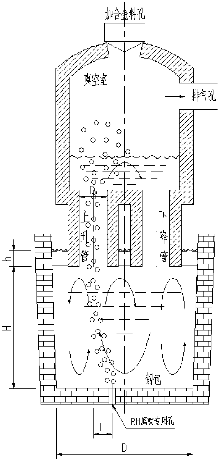
[0038] (1) After the LF refining is completed and the ladle enters the RH refining station, connect the blowing pipe to the pre-set ladle bottom blowing hole for the circulating flow of the RH refining process, and connect the ladle bottom argon blowing system for standby;

[0039] (2) Insert the pre-vacuum RH dipping tube under the liquid steel surface, and the RH dipping tube is immersed at a depth of 400mm; then vacuumize, the pressure of the vacuum chamber is controlled at 100Pa, and the riser of the RH dipping tube is adjusted to increase the gas flow rate to a stable value of 1500NL / min;

[0040] (3) Open the bottom blowing argon control valve, adjust the pressure and flow rate of the bottom blowing argon to be stable, and use the bottom center line of ...

Embodiment 3

[0050] For iron and steel smelting processes using RH as a refining means to produce silicon steel, home appliance panels and other steel types, the refining method of increasing the circulating flow rate of RH molten steel in this embodiment is also applicable. Due to different steel types and RH equipment parameters, the control conditions of RH vacuum pressure, lifting gas flow, ladle bottom blowing gas flow and ladle treatment after refining are also different during the RH refining process.

[0051] It is worth noting that, in addition to the above-mentioned steel types, the present invention is not limited to the steel types in the above-mentioned embodiments, and is also applicable to other types of steel types that adopt the RH refining process in the production process.

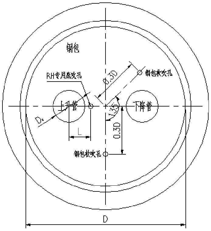
[0052] It should be noted that the single hole position parameter L and the lifting gas flow rate Q1 and the bottom blowing gas flow rate Q1 are provided in the present invention. 2 Relational formul...


PUM


Abstract

The invention provides a method for increasing the molten steel circulating flow quantity in the RH refining process and belongs to the technical field of molten steel refining. According to the method for increasing the molten steel circulating flow quantity in the RH refining process, a process procedure of converter / electric furnace-refining RH-continuous casting is adopted to produce high-quality pure steel, in the RH refining process, by means of utilization of an existing steel ladle argon bottom blowing system, argon is blown into the bottom of a steel ladle, argon bubbles blown in thebottom move along with a molten steel flow field, molten steel is lifted to enter an RH dipping pipe ascending pipe, coordinated control between steel ladle argon bottom blowing and dipping pipe inside gas lifting is realized, so that adverse effects in actual production that the air blowing hole position of an RH dipping pipe cannot be remolded and the lifting gas flow quantity is too large to blow through the molten steel inside the dipping pipe to reduce the lifting driving force instead are overcome, and the purpose of increasing the steel circulating flow quantity in the RH refining process is finally achieved. The method for increasing the molten steel circulating flow quantity in the RH refining process has the advantages of being simple and reliable, high in operability and convenient to realize, the RH circulating flow quantity is increased, the decarbonization efficiency is high, the refining time is obviously shortened, and the molten steel purity is improved.

Description

technical field [0001] This invention belongs to the technical field of molten steel refining, and in particular provides a method for increasing the circulating flow rate of molten steel in the RH refining process. Through this method, the reaction efficiency of molten steel in the RH refining process can be improved, the decarburization efficiency of molten steel can be improved, the refining time can be shortened, and the refining process can be optimized. Refining effect, improving the cleanliness of molten steel, thus playing a vital role in improving steel quality, increasing the brand and economic benefits of steel enterprises. Therefore, the present invention has important reference and guiding significance for the smelting of high-quality pure steel (such as IF steel, bearing steel, silicon steel, etc.). Background technique [0002] With the progress of society and the improvement of customers' requirements for products, how to produce clean steel efficiently, stab...

Claims


Application Information

Patent Timeline
Patent Type & Authority Applications(China)
IPC IPC(8): C21C7/10C21C7/072
CPCC21C7/072C21C7/10
Inventor 林路侯中晓杨勇汪成义何赛吴伟杨利彬王杰
Owner CENT IRON & STEEL RES INST
Why Eureka
Try Eureka