Supercharge Your Innovation With Domain-Expert AI Agents!

Mixing device for engine tail gas aftertreatment system

A tail gas post-treatment and mixing device technology, which is applied to exhaust devices, engine components, machines/engines, etc., can solve the problems of urea and exhaust gas mixing uniformity, and achieve good mixing uniformity and high gas flow velocity distribution uniformity Effect

Inactive Publication Date: 2019-04-19
HEBEI YILI RUBBER & PLASTIC GROUP
View PDF6 Cites 3 Cited by
  • Summary
  • Abstract
  • Description
  • Claims
  • Application Information

AI Technical Summary

Problems solved by technology

Due to the great difference in the direction of the airflow entering the mixer in the U-shaped and inline after-treatment devices, the mixing uniformity of urea and exhaust gas is greatly affected due to the difference in the direction of the intake air

Method used


Image

  • Mixing device for engine tail gas aftertreatment system
  • Mixing device for engine tail gas aftertreatment system
  • Mixing device for engine tail gas aftertreatment system

Examples


Embodiment Construction

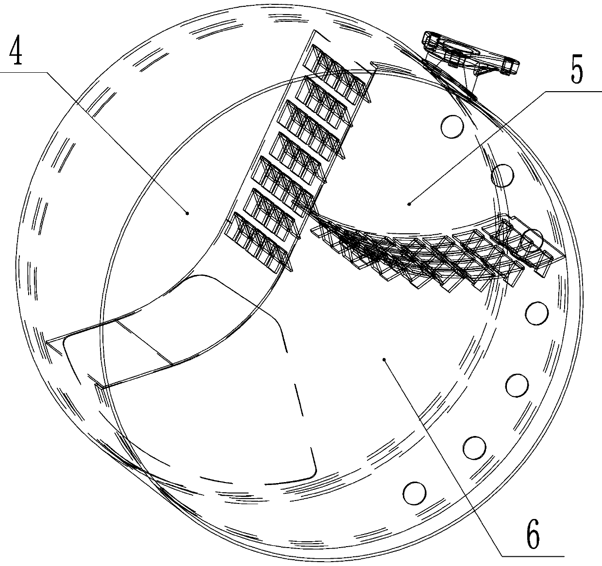
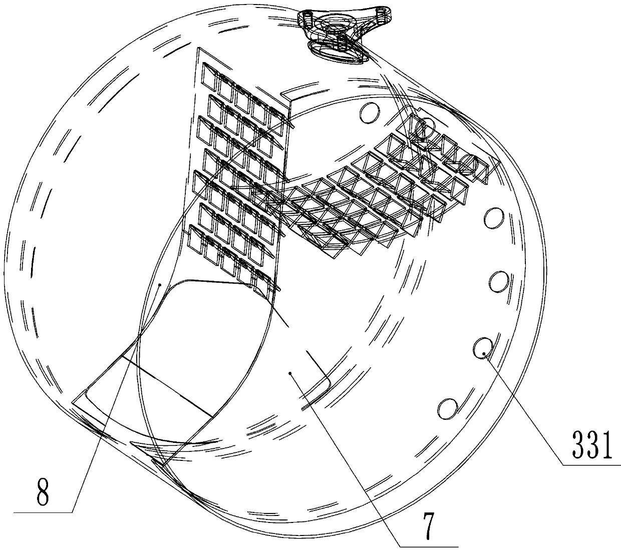
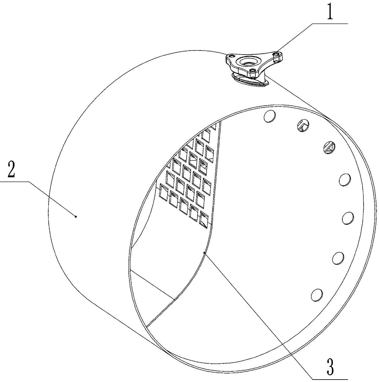
[0033] Such as Figure 1-10 As shown, the present invention includes a shell 2 and an inner assembly 3 thereof; The first deflector 31 and the second deflector 32; the first deflector 31 and the second deflector 32 form a "human" shape, and the second deflector 32 is located below the first deflector 31, thus the first deflector A deflector 31 , a second deflector 32 , a front baffle 33 and a rear baffle 34 constitute three spaces.

[0034] The shell 2 is located on the outer periphery between the front baffle 33 and the rear baffle 34 ; the first deflector 31 and the second deflector 32 are located inside the shell 2 .

[0035] A urea inlet 1 is provided at the upper casing 2 between the first deflector 31 and the second deflector 32; the urea inlet 1 is connected to the urea nozzle, and the urea nozzle is connected to the casing 2 through the urea nozzle seat .

[0036] The first deflector 31 and the second deflector 32 are respectively provided with one or more blades, a...


PUM


Abstract

The invention relates to a mixing device for an engine tail gas aftertreatment system. The mixing device for the engine tail gas aftertreatment system comprises a cylinder skin and an inner assembly of the mixing device, wherein the inner assembly comprises a front baffle, a rear baffle, a first flow guide plate and a second flow guide plate, the first flow guide plate and the second flow guide plate are arranged between the front baffle and the rear baffle, an urea inlet is formed at the portion, above a portion between the first flow guide plate and the second flow guide plate, of the cylinder skin, one or more blades are obliquely arranged on each of the first flow guide plate and the second flow guide plate, each blade corresponds to one blade opening, an air inlet is formed in the side, located on the first flow guide plate, of the front baffle, the air inlet and the second flow guide plate are located on the two sides of the first flow guide plate correspondingly, and an air outlet is formed in the portion, located below the first flow guide plate and the second flow guide plate, of the rear baffle. According to the mixing device, the mixing effect is good, the influence of the air inlet direction difference is avoided, and the mixing uniformity of the urea and the tail gas is improved.

Description

technical field [0001] The invention relates to the field of automobile exhaust systems, in particular to a mixing device used in an engine exhaust aftertreatment system. Background technique [0002] Due to the limitation of the layout space of the whole vehicle, the layout of the after-treatment device is varied. U-shaped, straight and square arrangements are common. In order to reduce development costs, modular design is a trend. Because the direction of the airflow entering the mixer in the U-shaped and inline after-treatment devices is very different, the mixing uniformity of urea and exhaust gas is greatly affected due to the difference in the direction of the air intake. Therefore, it is necessary to develop a mixing device for a post-treatment system with good mixing uniformity of urea and gas. Contents of the invention [0003] The technical problem to be solved by the present invention is to provide a mixing device with good mixing effect for an engine exhaust...

Claims


Application Information

Patent Timeline
Patent Type & Authority Applications(China)
IPC IPC(8): F01N3/20F01N3/28F01N13/08
CPCF01N3/2066F01N3/28F01N13/08
Inventor 薛红娟李江飞乔宝英史运帅
Owner HEBEI YILI RUBBER & PLASTIC GROUP
Features
  • R&D
  • Intellectual Property
  • Life Sciences
  • Materials
  • Tech Scout
  • Unparalleled Data Quality
  • Higher Quality Content
  • 60% Fewer Hallucinations
Learn More