
Waste heat recovery system for hydrophobic expansion container of waste power plant

A technology of waste heat recovery system and water-repellent expansion vessel, which is applied in the direction of feed water heater, preheating, supplementary feed water, etc., can solve the problems that affect the safe and civilized production of power plants, increase the loss of soda and heat, and increase the unsafe factors in the plant area, etc., to achieve Avoid the direct exhaust of exhaust steam, save energy, and benefit the effect of safe production

Pending Publication Date: 2019-04-19
CHENGDU XINGRONG RENEWABLE ENERGY CO LTD
View PDF0 Cites 0 Cited by
  • Summary
  • Abstract
  • Description
  • Claims
  • Application Information

AI Technical Summary

Problems solved by technology

In many waste incineration power plants, the exhaust pipes of the drainage expanders in the steam turbine rooms pass through the walls and lead to the outside of the plant to be discharged directly to the air. A large amount of hydrophobic exhaust is directly discharged to the air through the exhaust pipes, resulting in the loss of steam, water and heat, and also affects the power plant. At the same time, in the design stage, the design institute has already selected the parameters of the expansion vessel according to the drainage parameters of the power plant. When the design is changed in the later stage, the overload operation of the expansion vessel and the loss of soda and heat will occur. Further aggravation may also lead to personal injury of the inspectors in this area and increase the unsafe factors in the factory area

Method used


Image

  • Waste heat recovery system for hydrophobic expansion container of waste power plant

Examples


Embodiment Construction

[0020] The present invention will be further described below in conjunction with the accompanying drawings.

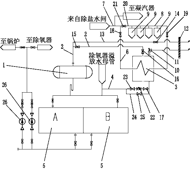
[0021] Such as figure 1 As shown, the waste heat recovery system is used for the waste heat recovery system of the expansion vessel of the garbage power plant. The bottom of the expansion vessel 1 is connected to the drainage box 5, and the drainage box 5 is connected to the deaerator 9 and the boiler through the drainage pump 26 (not shown in the figure). The top of the hydrophobic expander 1 is connected with an exhaust pipe 2, and the exhaust pipe 2 is connected with a heat exchanger 3. The heat exchanger 3 includes a shell side and a tube side. The top of the shell side has a steam inlet, and the bottom has a condensate outlet. The tube side includes desalted water inlet and desalted water outlet, exhaust pipe 2 is connected to steam inlet, condensed water outlet is connected to drain tank 5 through condensed water pipe 4, desalted water inlet is connected to desal...


PUM


Abstract

The invention relates to the technical field of a hydrophobic expansion container of a waste power plant, and discloses a waste heat recovery system for the hydrophobic expansion container of the waste power plant. The top of the hydrophobic diffusion container is connected with a steam exhaust pipe, the steam exhaust pipe is connected with a heat exchanger, the heat exchanger comprises a shell pass and a tube pass, a steam inlet is formed in the top of the shell pass, a condensate water outlet is formed in the bottom of the shell pass, the tube pass comprises a desalted water inlet and a desalted water outlet, the steam exhaust pipe is connected with the steam inlet, the condensate water outlet is connected with a hydrophobic tank through a condensate water pipe, the desalted water inletis connected with a desalted water main pipe through a water inlet pipe, the desalted water outlet is connected with a water outlet pipe, a plurality of deaerators are connected to the water outlet pipe in parallel, desalted water in the desalted water main pipe can be heated by the heat exchanger and then fed into the deaerators. The heat exchanger can be used for recycling heat in steam discharged from the hydrophobic expanding container to the desalted water, condensate water formed by steam exhaust is returned to the hydrophobic tank and can be reused, the steam discharge of the hydrophobic diffusion container is effectively prevented from being directly discharged, the energy is saved, and the safe production is facilitated.

Description

technical field [0001] The invention relates to the technical field of drain expansion vessels of garbage power plants, in particular to a waste heat recovery system used for drain expansion vessels of waste power plants. Background technique [0002] The function of the drain expander is to expand the drain in the pressure drain pipeline to reduce the pressure, recover the drain, and reduce the loss of soda water. In many waste incineration power plants, the exhaust pipes of the drainage expanders in the steam turbine rooms pass through the walls and lead to the outside of the plant to be discharged directly to the air. A large amount of hydrophobic exhaust is directly discharged to the air through the exhaust pipes, resulting in the loss of steam, water and heat, and also affects the power plant. At the same time, in the design stage, the design institute has already selected the parameters of the expansion vessel according to the drainage parameters of the power plant. Wh...

Claims


Application Information

Patent Timeline
IPC IPC(8): F22D1/50F22D11/06F28D7/00
CPCF22D1/50F22D11/06F28D7/00
Inventor 邓纲刘永华钟大元汪洋徐方利冉茂国
Owner CHENGDU XINGRONG RENEWABLE ENERGY CO LTD
Learn More