Cyclone pulverized coal combustion device adopting smoke recirculation device and pre-combustion chamber
A flue gas recirculation and combustion device technology, which is applied to the combustion of block fuel and gaseous fuel, the combustion of liquid fuel and gaseous fuel, the combustion of gaseous fuel and powder fuel, etc., and can solve the problem of fly ash combustibles High content, high NOx emissions, poor combustion stability, etc., to achieve the effects of increasing stability and combustion intensity, strengthening radial staged combustion, and strengthening the degree of staged combustion
- Summary
- Abstract
- Description
- Claims
- Application Information
AI Technical Summary
Problems solved by technology
Method used
Image
Examples
specific Embodiment approach 1
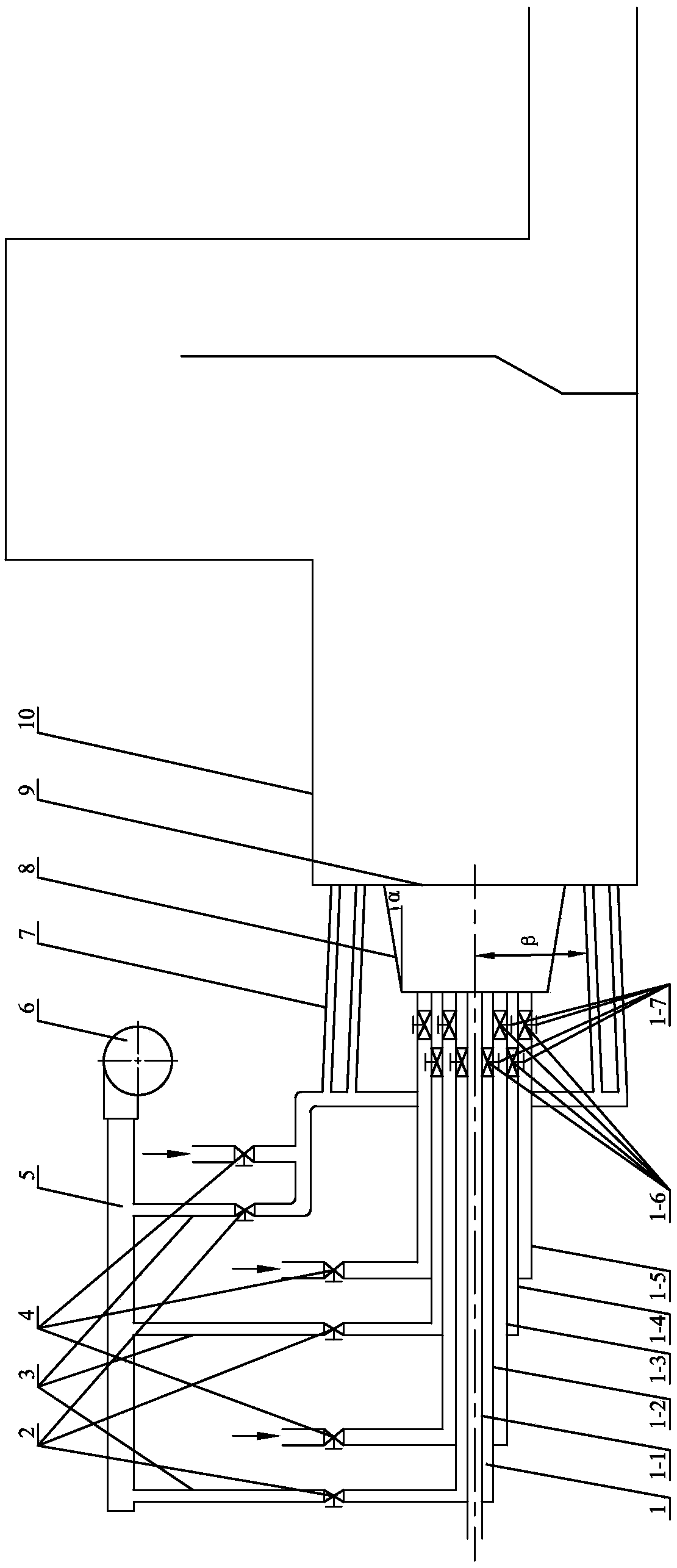
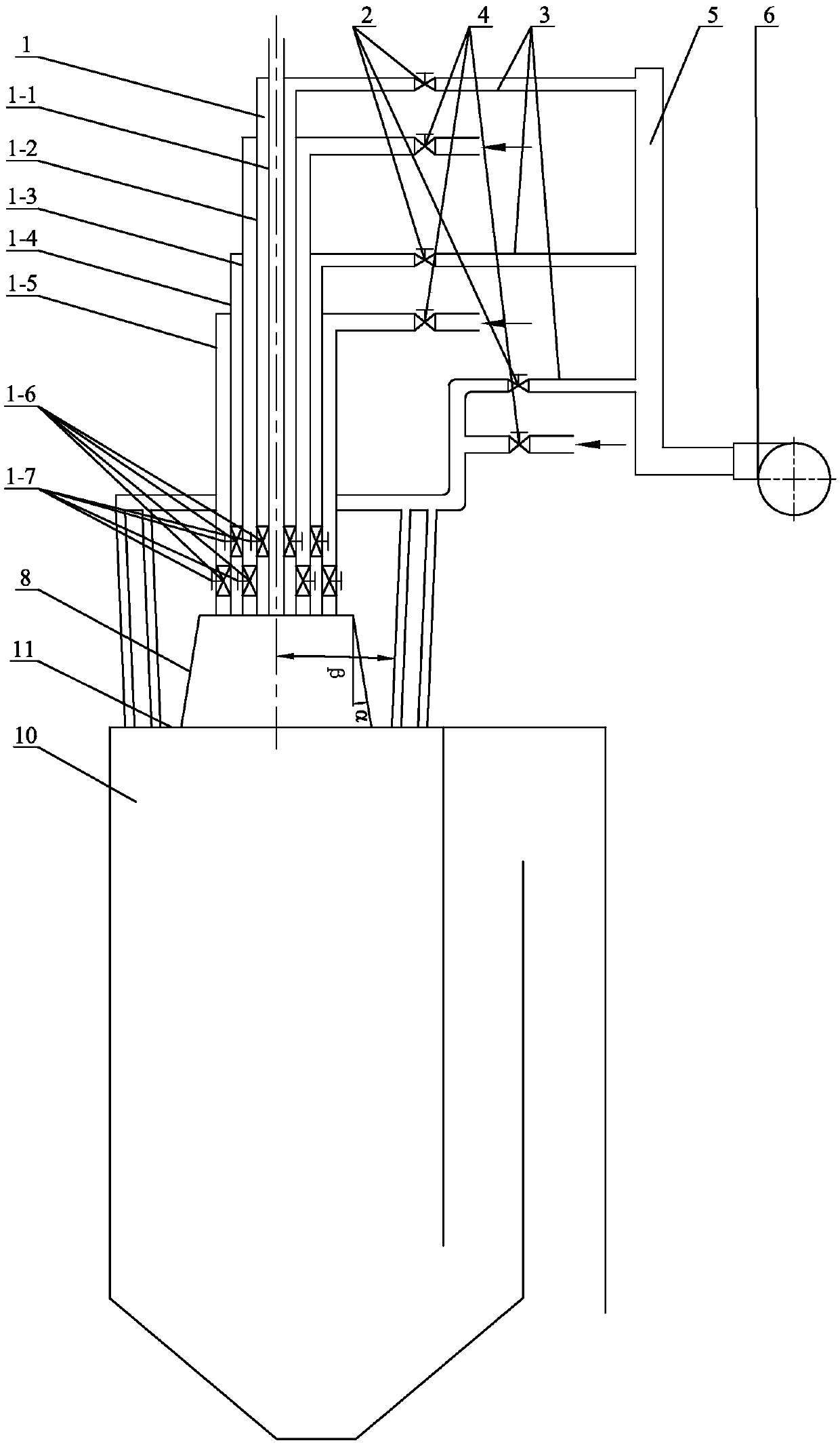
[0029] Specific implementation mode 1: Combination figure 1 with figure 2 To describe this embodiment, a swirling pulverized coal combustion device using flue gas recirculation and a pre-combustion chamber in this embodiment includes a pulverized coal combustion system and a flue gas recirculation system. The pulverized coal combustion system includes swirling pulverized coal The burner 1, the pre-combustion chamber 8 and a plurality of separated secondary air nozzles 7, the swirling pulverized coal burner 1 is connected to the boiler 10 through the pre-combustion chamber 8, and the swirling pulverized coal burner 1 is coaxially arranged in the pre-combustion chamber 8 At the front end, the outlet of the swirling pulverized coal burner 1 is flush with the inner wall of the pre-combustion chamber 8 (that is, the primary air duct 1-1, the inner flue gas recirculation duct 1-2, the inner secondary air duct 1-3, and the outer smoke The outlets of the air recirculation air ducts 1-...
specific Embodiment approach 2
[0034] Specific implementation manner two: combination figure 1 To illustrate this embodiment, the boiler 10 of this embodiment is a horizontal boiler, and the swirling pulverized coal burner 1 is connected and arranged on the front wall 9 of the horizontal boiler through a pre-combustion chamber 8. In this way, the inlet ends of the plurality of separated secondary air nozzles 7 are connected with secondary air and recirculated flue gas, and the outlet ends of the plurality of separated secondary air nozzles 7 are arranged on the front wall 9 of the horizontal boiler. The other composition and connection relationship are the same as in the first embodiment.
specific Embodiment approach 3
[0035] Specific implementation mode three: combination figure 2 To illustrate this embodiment, the boiler 10 of this embodiment is a vertical boiler, and the swirling pulverized coal burner 1 is connected and arranged on the roof 11 of the vertical boiler through a pre-combustion chamber 8. In this way, the inlet ends of the plurality of separated secondary air nozzles 7 are connected to the secondary air and the recirculated flue gas, and the outlet ends of the plurality of separated secondary air nozzles 7 are arranged on the roof 11 of the vertical boiler. Other components and connection relationships are the same as those in the first or second embodiment.
PUM
 Abstract
Description
Claims
Application Information
 - R&D
- Intellectual Property
- Life Sciences
- Materials
- Tech Scout
- Unparalleled Data Quality
- Higher Quality Content
- 60% Fewer Hallucinations
Browse by: Latest US Patents, China's latest patents, Technical Efficacy Thesaurus, Application Domain, Technology Topic, Popular Technical Reports.
© 2025 PatSnap. All rights reserved.Legal|Privacy policy|Modern Slavery Act Transparency Statement|Sitemap|About US| Contact US: help@patsnap.com


