Static laser speckle reduction method combining multimode optical waveguide and diffractive optical device

A multi-mode optical waveguide and diffractive optics technology, applied in optical components, laser optical equipment, optics, etc., can solve the problems of insufficient speckle suppression effect, slow response time, large size, etc. Fast, small size effect

Active Publication Date: 2019-04-19
ZHEJIANG UNIV OF TECH
View PDF5 Cites 2 Cited by
  • Summary
  • Abstract
  • Description
  • Claims
  • Application Information

AI Technical Summary

Problems solved by technology

[0004] In order to overcome the shortcomings of the prior art, such as insufficient speckle suppression effect, poor reliability, complex system, slow response time, need for power supply, large size, and high cost, the present invention provides a high reliability, no need for power supply, and fast response time. , no mechanical operating mechanism, simple system, small size, a

Method used


Image

  • Static laser speckle reduction method combining multimode optical waveguide and diffractive optical device
  • Static laser speckle reduction method combining multimode optical waveguide and diffractive optical device
  • Static laser speckle reduction method combining multimode optical waveguide and diffractive optical device

Examples


Embodiment 1

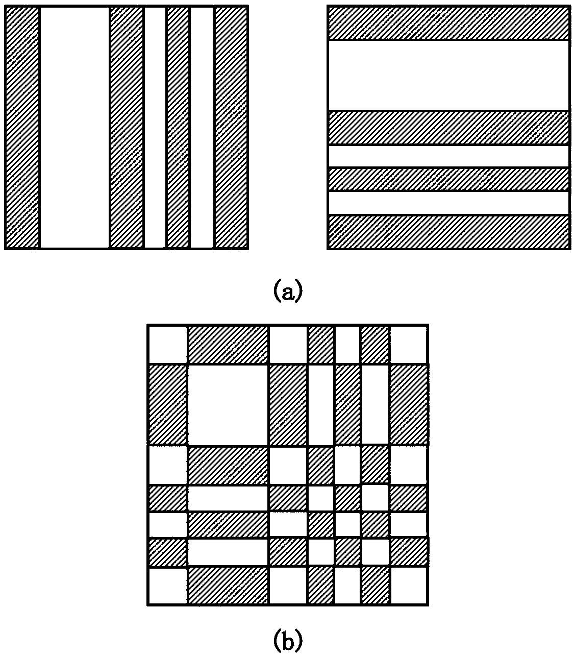
[0055] A static laser speckle suppression method combining a multimode optical waveguide and a diffractive optical device, wherein the diffractive optical device adopts two one-dimensional pseudo-random sequence binary codes to be orthogonally superimposed into a two-dimensional binary code (see attached figure 2 ), the overlapping angle is 90 degrees, the minimum coding width of the binary code is 6 microns, and the number of bits of the pseudo-random sequence code is 13.

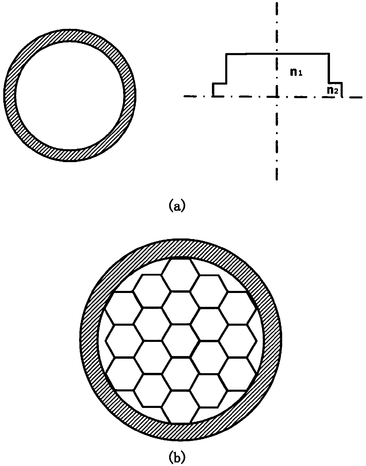
[0056] See attached image 3 (a), the multimode optical waveguide is a multimode optical fiber, the core layer of the multimode optical fiber is a cylindrical optical waveguide with a diameter of 400 microns, and the length l of the multimode optical fiber is 1500 mm.

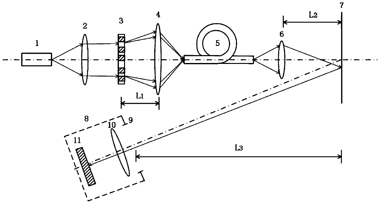
[0057] See attached figure 1 , the static laser speckle suppression method combined with multimode optical waveguide and diffractive optical device, its function is realized by the static laser speckle suppression system. The static lase...

Embodiment 2

[0061] See attached image 3 (b), the multimode optical waveguide adopts a multimode optical fiber bundle, the diameter of the multimode optical fiber bundle is 5 millimeters, and each multimode optical fiber in the multimode optical fiber bundle has a circumcircle diameter of 25 microns The hexagonal cylindrical optical waveguide, the length l of the multimode optical fiber bundle is 2500 mm. Other implementation parameters and processes are the same as in Example 1.

[0062] The laser speckle suppression effect is a speckle suppression factor of 2.4.


PUM

PropertyMeasurementUnit
Diameteraaaaaaaaaa
Lengthaaaaaaaaaa
Diameteraaaaaaaaaa

Abstract

The invention provides a static laser speckle reduction method combining a multimode optical waveguide and a diffractive optical device. The method comprises the following steps that Step 1, a laser beam is collimated and then input into the diffractive optical device, the diffractive optical device outputs the incident collimated laser beam as diffraction beams with different diffraction orders;Step 2, the diffraction beams with the different diffraction orders are focused by a lens, the focused beams are input into the multimode optical waveguide, the multimode optical waveguide modulates the transmission delay of different diffracted beams, so that the diffraction beams of all diffraction orders are output from the multimode optical waveguide at the delay difference delta T; Step 3, the diffraction beams output at different delays are collected by an imaging lens and imaged on a projection screen, the projection screen is provided with a rough surface, an image on the projection screen is received and processed by a digital camera, and the static laser speckle suppression is achieved. The static laser speckle reduction method combining the multimode optical waveguide and the diffractive optical device has the advantages that the reliability is high, electric energy supply is not needed, the response time is short, no mechanical running mechanism is needed, the system is simple, the size is small, and the cost is low.

Description

technical field [0001] The invention belongs to the field of laser display projection, and in particular relates to a fully static space / time hybrid laser speckle suppression method combined with a multimode optical waveguide and a diffractive optical device. Background technique [0002] Laser projection display system is getting more and more attention and welcome because of its rich colors, high picture quality, long life, high reliability, high efficiency, low energy consumption and other advantages. However, since laser light is highly coherent light, it will inevitably produce a picture noise called laser speckle. Laser speckle is formed by random coherent superposition of signals, which seriously affects the quality of the image. In the field of laser projection display, speckle will degrade the image quality of projection display, cause viewers to experience symptoms such as fatigue and dizziness, seriously affect the experience of laser projector users, and is the c...

Claims


Application Information

Patent Timeline
IPC IPC(8): G02B27/48
CPCG02B27/48H01S3/005
Inventor 乐孜纯董文
Owner ZHEJIANG UNIV OF TECH
Why Eureka
Try Eureka