
A method for calculating a complex structure radiation sound field in a marine acoustic channel

A technology of complex structures and calculation methods, applied in calculation, design optimization/simulation, and special data processing applications, etc., can solve the problems of limited boundary element method application, sharp increase in computation and storage, and complex structural acoustic radiation in difficult ocean channels, etc. problem, achieve the effect of reducing memory consumption and good algorithm adaptability

Pending Publication Date: 2019-04-19
中国船舶重工集团公司第七六〇研究所
View PDF0 Cites 9 Cited by
  • Summary
  • Abstract
  • Description
  • Claims
  • Application Information

AI Technical Summary

Problems solved by technology

However, the traditional acoustic boundary element method has the following disadvantages: (1) The free-field Green’s function used in the traditional boundary element method is not suitable for dealing with the acoustic radiation problem in a bounded space; (2) the node-to-node calculation method adopted by the boundary element method, The amount of calculation is proportional to the cube of the total number of degrees of freedom
When solving large-scale problems, the amount of calculation and storage will increase dramatically, which greatly limits the application of boundary element method in large-scale engineering problems
Therefore, the traditional boundary element method is difficult to use to calculate the complex structure-acoustic radiation problem in the ocean channel environment

Method used


Image

  • A method for calculating a complex structure radiation sound field in a marine acoustic channel
  • A method for calculating a complex structure radiation sound field in a marine acoustic channel
  • A method for calculating a complex structure radiation sound field in a marine acoustic channel

Examples


Embodiment Construction

[0012] The specific embodiments of the present invention will be described in detail below in conjunction with the technical solution and the drawings. The following examples are used to illustrate the present invention, but cannot be used to limit the scope of the present invention.

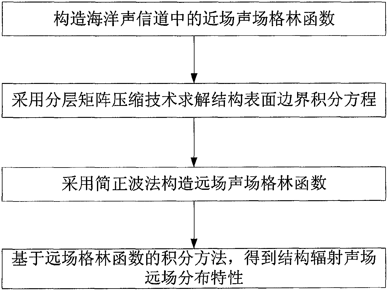
[0013] The flowchart of the calculation method of the present invention is as figure 1 As shown, it can be divided into four steps:

[0014] step one:

[0015] Calculate the Green's function of the near-field sound field in the ocean acoustic channel.

[0016] (1) When the target is not very close to the waveguide interface, the effect of multiple acoustic reflections at the waveguide boundary can be ignored. Green's function is approximated by free-field Green's function.

[0017] Where r=|P-Q| (1)

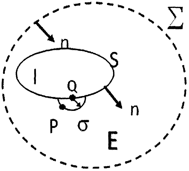
[0018] Border areas such as figure 2 As shown, E, S, and I represent the exterior, surface, and interior of the boundary element model, respectively, Σ is a spherical boundary at infinity, Q is a point on ...


PUM


Abstract

The invention discloses a method for calculating a complex structure radiation sound field in a marine acoustic channel, and belongs to the technical field of acoustic numerical calculation. The limitation that a traditional boundary element method is only suitable for free field sound field calculation is broken through, and a sound field Green function in an ocean sound channel is established. Ahierarchical matrix compression technology is adopted to divide a radiation impedance matrix into a series of hierarchical matrix blocks with different sizes, and an iteration method is further utilized to solve a matrix equation. Compared with the prior art, the method has the effects and benefits that the acoustic calculation function of the traditional boundary element method is expanded frominfinite uniform media to the bounded space of the ocean channel, and the influence of sea surface, seabed boundary and sound velocity gradient distribution can be considered. And on the other hand, the radiation impedance matrix is subjected to hierarchical compression, the consumption of a computer memory is greatly reduced by utilizing the low-rank characteristic approximate decomposition of the matrix block, the influence of the diversity of a sound field Green function under the complex marine channel condition is avoided, and the algorithm adaptability is good.

Description

Technical field [0001] The invention relates to an acoustic numerical calculation method, in particular to a fast boundary element calculation method for the radiated sound field of a complex structure in a marine acoustic channel. Background technique [0002] The ocean acoustic channel has a great influence on the shell vibration and acoustic radiation. The calculation needs to consider the reflection and absorption of the bottom and water surface. The calculation of far-field propagation depends more on the acoustic channel factors such as the sound velocity gradient distribution in the sea area and the sea surface and seabed geological conditions. This makes the calculation of the sound field radiated by the structure in the ocean channel difficult. [0003] In the prior art, people have separately studied the calculation of the sound field radiated by complex structures and the propagation of sound waves in ocean channels. The former treats the seawater medium into an ideal u...

Claims


Application Information

Patent Timeline
Patent Type & Authority Applications(China)
IPC IPC(8): G06F17/50
CPCG06F30/20
Inventor 王纪会贾兵王振山
Owner 中国船舶重工集团公司第七六〇研究所
Learn More