Method and system for distributed energy control

A distributed energy and control method technology, applied in the field of distributed energy control methods and systems, can solve problems such as the inability of a single family to meet basic electricity consumption and power grid power outages, and achieve the effect of maximizing utilization

Inactive Publication Date: 2019-04-19
CHINA ELECTRIC POWER RES INST +3
View PDF6 Cites 5 Cited by
  • Summary
  • Abstract
  • Description
  • Claims
  • Application Information

AI Technical Summary

Problems solved by technology

[0003] In order to solve the problem in the prior art that single-family households cannot meet the basic power consumption due to power outages in the power grid, the present invention provides a system and method for formulating an energy Internet control strategy

Method used


Image

  • Method and system for distributed energy control
  • Method and system for distributed energy control
  • Method and system for distributed energy control

Examples


Embodiment 1

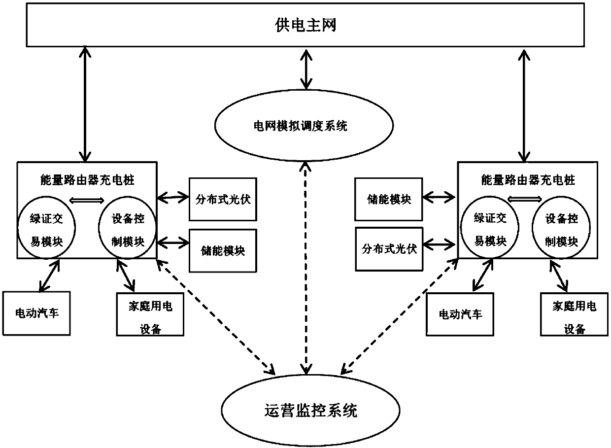
[0057] The first step is to establish a multi-solar-storage system model. The schematic diagram of the solar-storage-charge model is as follows: figure 2 As shown; the second step adopts a hierarchical energy management method, in which the upper layer (inter-station) adopts the method based on the average energy proportion, and the lower layer (intra-station) adopts a rule-based energy management strategy.

[0058] The energy Internet distributed control strategy of the integrated optical storage and charging system is realized through the following steps:

[0059] Establish a photovoltaic storage charging model: according to the needs of the project demonstration base, build a photovoltaic charging station system for 20 households, and connect the stations to the main grid through an AC bus. Each household photovoltaic charging station system includes photovoltaic systems, battery systems, main grids, and battery vehicles (1 car), household electrical equipment.

[0060] T...

Embodiment 2

[0076] Based on the same inventive concept, this solution also provides a distributed energy control system:

[0077] A distributed energy control system, comprising:

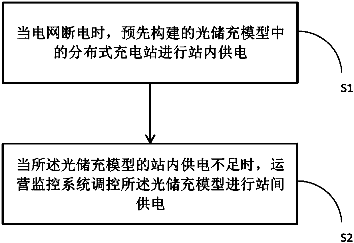
[0078] In-station power supply module: When the power grid is cut off, the distributed charging station in the pre-built optical storage charging model will provide in-station power supply;

[0079] Inter-station power supply module: when the internal power supply of the optical storage and charging model is insufficient, the operation monitoring system regulates the optical storage and charging model to provide inter-station power supply;

[0080] The power supply module in the station includes: model building sub-module;

[0081] The solar-storage-charging model constructed by the model construction sub-module includes: a plurality of distributed charging stations in the area, and each distributed charging station is connected to the physical layer line of the power grid through a power transmission line.

...

Embodiment 3

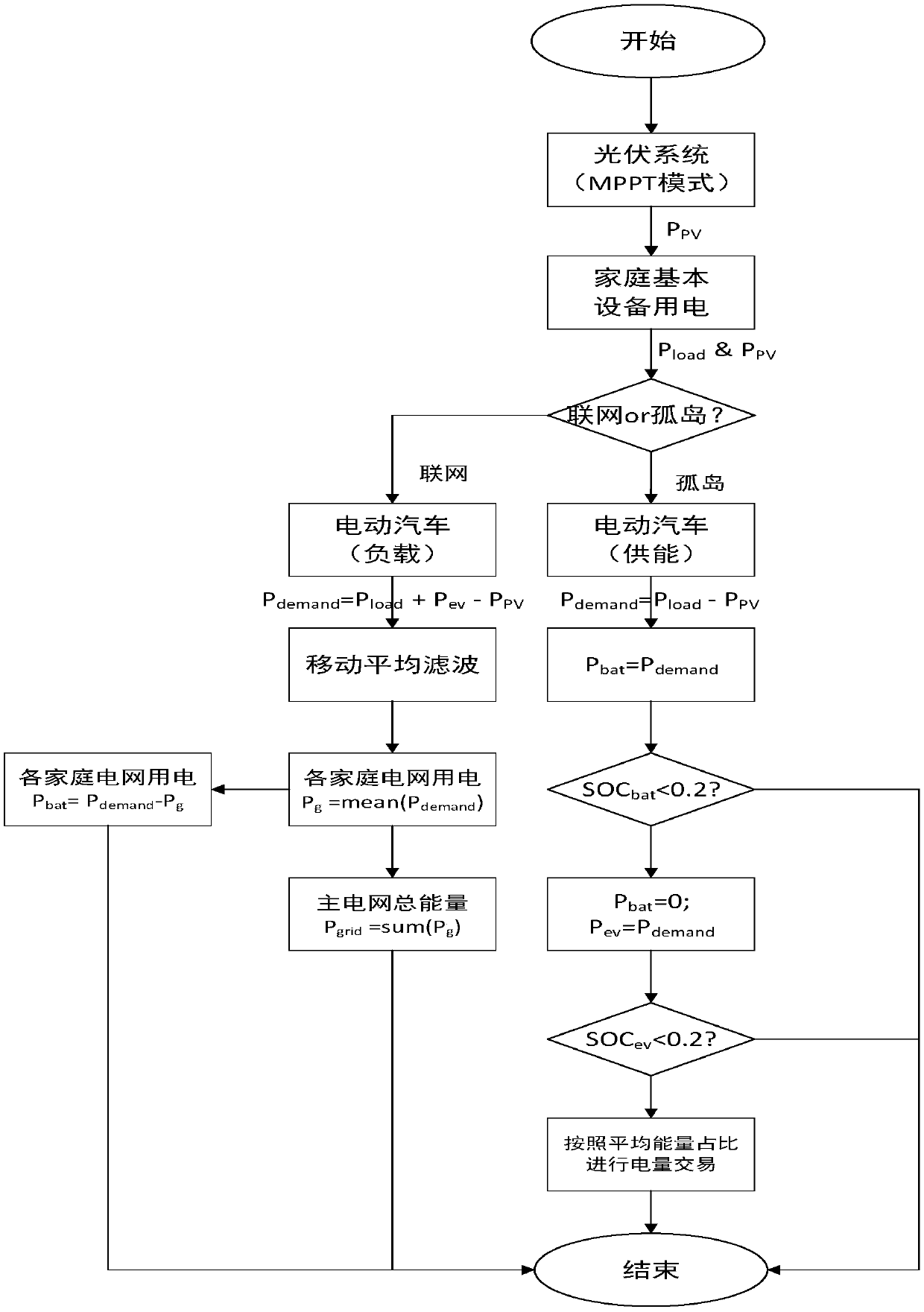
[0112] image 3 It is a flow chart of the energy management strategy. In the figure, the photovoltaic system works in the maximum power point tracking (MPPT) mode, and its power is P pv . The whole system must meet the power consumption P of each family's basic equipment load

[0113] The main power grid may work in network mode or island mode. In different modes, household electric vehicles have different roles (load or energy supply), and the system has different energy management strategies.

[0114] In the networked state: the power grid and the battery system jointly undertake the basic power consumption of households and electric vehicles. In the figure, P demand is the energy shared by the grid and the battery system, P ev is the energy power of the electric vehicle, P load It is the electricity consumption of basic equipment in each family. The photovoltaic system works in the maximum power point tracking (MPPT) mode, and its power is P pv , P grid Refers to the...


PUM


Abstract

A distributed energy control method comprises: when a power grid is powered off, a distributed charging station in a pre-constructed optical storage charging model supplying power in a station; when the in-station power supply of the optical storage and charging model is insufficient, the operation monitoring system regulating and controling the optical storage and charging model to carry out inter-station power supply; wherein the optical storage and charging model comprises a plurality of distributed charging stations in an area, and each distributed charging station is connected with a physical layer circuit of a power grid through a power transmission wire. According to the scheme, an efficient energy management strategy is formulated for the photovoltaic storage and charging integrated system and used for managing energy flow of a plurality of photovoltaic charging levels, the phenomenon that a family cannot meet basic electricity consumption due to power failure of a power grid is avoided, and maximum utilization of photovoltaic power generation is achieved.

Description

technical field [0001] The invention relates to the technical field of power grid energy management, in particular to a distributed energy control method and system. Background technique [0002] With the development of smart parks and the development of electric vehicles, the proportion of photovoltaic power generation in smart parks continues to increase. In the future, a large number of home charging stations integrating photovoltaic power generation will be put into operation, but the actual operation of different home charging stations is different, because Different charging stations have different electric vehicle charging time, electric vehicle types, and charging station capacity parameters. Therefore, how to efficiently manage the energy of multiple home charging stations in the smart park, so that multiple home charging stations can be effectively combined, It is of great significance to support and supplement each other, avoid the phenomenon that a single househo...

Claims


Application Information

Patent Timeline
Patent Type & Authority Applications(China)
IPC IPC(8): H02J3/38H02J3/28H02J3/06
CPCH02J3/383H02J3/06H02J3/28H02J2203/20Y02E70/30Y02E10/56
Inventor 张元星蒋林洳江冰许娟婷李涛永马澄斌刘永相许庆强张晶李康肖宇华刁晓虹李斌冯义张宝平闫华光郭炳庆覃剑仇新宇吴涛易江腾黄健
Owner CHINA ELECTRIC POWER RES INST
Why Eureka
Try Eureka