Metal component field high-energy thermal cutting and hole forming device

A metal component and hole-forming device technology, which is applied in the field of high-energy thermal cutting hole-forming devices for metal components in the field, can solve problems such as unsafety, poor orientation, and high energy consumption, and achieve fast combustion reaction speed, fast cutting rate, and low energy consumption Effect

Pending Publication Date: 2019-04-23
ARMY ENG UNIV OF PLA
View PDF12 Cites 3 Cited by
  • Summary
  • Abstract
  • Description
  • Claims
  • Application Information

AI Technical Summary

Problems solved by technology

[0008] The purpose of the present invention is to address the deficiencies of the prior art, to provide a field high-energy thermal cutting hole-forming device for metal components, to solve the problem of unsafe conditions in the storage and transportation process of using high-sensitivity pyrotechnic elements in the prior art. Factors, do not use remote operation, poor orientation, high energy consumption

Method used


Image

  • Metal component field high-energy thermal cutting and hole forming device
  • Metal component field high-energy thermal cutting and hole forming device
  • Metal component field high-energy thermal cutting and hole forming device

Examples


Embodiment 1

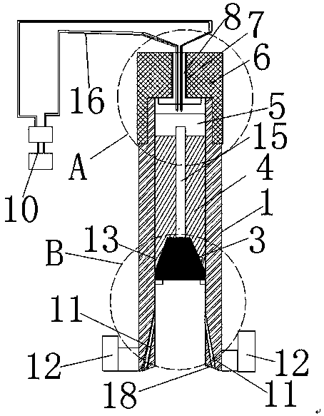
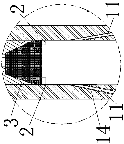
[0036] Example 1. Such as Figure 1-7 As shown, an outdoor high-energy thermal cutting hole-forming device for metal components is characterized in that: it includes a charge barrel 1, and the charge barrel 1 is sequentially provided with an aluminum body whose central axis coincides with the center axis of the charge barrel 1 from bottom to top. The retaining ring 2, the frustum-shaped frustum plug 3, the thermite layer 4, and the ignition agent layer 5 made of ceramics or graphite, the radial outer peripheral surface of the bottom of the frustum plug 3 are tight Mount the radially inner peripheral surface of the drug barrel 1 and the bottom surface of the cone plug 3 is connected to the top surface of the retaining ring 2; the retaining ring 2 is connected to the radially inner peripheral surface of the middle part of the charge barrel 1 and its top surface is perpendicular to The central axis of the charging barrel 1; the top of the charging barrel 1 is equipped with a top...

Embodiment 2

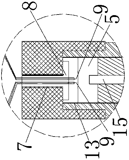
[0048] Example 2. Such as Figure 8-9 As shown, the difference between this embodiment and Embodiment 1 is that the insulating plug installation through hole 7 and the insulating plug 8 are all in the shape of a truncated cone with a small upper part and a larger lower part; the insulating plug 8 is threadedly connected with the insulating plug installation through hole 7.

Embodiment 3

[0049] Example 3. Such as Figure 10 As shown, the difference between this embodiment and Embodiment 1 is that the fixing device 12 includes connecting ears, and the connecting ears are connected to the object 17 to be punched through a wire rope 20. The object 17 to be punched is plate-shaped.


PUM

PropertyMeasurementUnit
densityaaaaaaaaaa
densityaaaaaaaaaa
densityaaaaaaaaaa

Abstract

The invention discloses a metal component field high-energy thermal cutting and hole forming device. The device comprises a charging barrel; an aluminum-made retainer ring, a frustum plug, a thermitelayer and an ignition agent layer are arranged in the charging barrel in sequence from bottom to top; a top cover is mounted at the top end of the charging barrel; a mounting through hole is vertically formed in the center of the top cover; an insulation plug is mounted in the mounting through hole; two ignition electrodes are vertically mounted on the insulation plug; multiple punching holes areformed in the lower part of the side wall of the charging barrel; multiple fixing devices for fixing the charging barrel on objects to be punched are arranged on the radial outer peripheral surface ofthe charging barrel; and a support sleeve is arranged between the frustum plug in the charging barrel and the objects to be punched. The hole forming device is high in energy density, high in combustion temperature, high in cutting pressure and suitable for quick emergency thermal cutting and underwater cutting of various steel structural parts in fields or battlefields under the conditions of noelectricity, no gas and no cutting equipment.

Description

technical field [0001] The invention relates to the field of emergency cutting, in particular to a hole-forming device for outdoor high-energy thermal cutting of metal components. Background technique [0002] Emergency cutting is an important technology for emergency installation, repair and demolition of field engineering facilities and equipment, and it is also an indispensable technology in battlefield repair. Statistics show that equipment parts are stuck, broken, perforated and other damages in the field or on the battlefield, which affect the performance of the equipment. Most of them need to be quickly solved by emergency cutting first. In earthquake, snow disaster, landslide, shipwreck and other disaster rescues and daily fire rescue, there is an urgent need for a portable and safe emergency cutting method. [0003] At present, the commonly used thermal cutting methods in field repairs are plasma cutting or gas cutting. Plasma cutting is a thermal cutting method t...

Claims


Application Information

Patent Timeline
Patent Type & Authority Applications(China)
IPC IPC(8): B23K31/02B23D79/00
CPCB23D79/00B23K31/02
Inventor 纪冲杨贵丽赵长啸谢兴博孙宇翔程良玉钟明寿李兴华
Owner ARMY ENG UNIV OF PLA
Why Eureka
Try Eureka