
Magnetic simulation muscle structure

A muscle and magnetic force technology, applied in the field of electromagnetic drive devices, can solve problems such as the inability to control the electromagnet to stay in a certain magnetic circuit position, the inability to realize the control of fine movements, and the inability to accurately control the connection stroke, etc., to achieve light weight and high The effect of acceleration and mechanical wear is small

Inactive Publication Date: 2019-04-26
广东协禾医业有限公司
View PDF0 Cites 0 Cited by
  • Summary
  • Abstract
  • Description
  • Claims
  • Application Information

AI Technical Summary

Problems solved by technology

[0003] Compared with the traditional non-linear motor drive, the new device driven by linear motor has the advantages of simple structure, no contact wear, low noise, high precision, flexible combination and fast speed, etc., but the characteristics of the linear motor itself determine its own defects. : For example, the edge effect caused by the on-off of the magnetic circuit and the installation air gap are large; in addition, the traditional gravitational attraction mechanism still has the connection stroke that cannot be accurately controlled by the attraction, which makes the attraction connection extremely abrupt
In other words, as long as the electromagnetic attraction is triggered, the electromagnet will directly change from a static state to a moving state and will not stop on the stroke, but until it is attracted to the magnetic coil, which will make it impossible to control the electromagnet. In terms of the position of the magnetic circuit, it is impossible to realize the control of fine movements in practical applications, and it is not practical at all.

Method used


Image

  • Magnetic simulation muscle structure
  • Magnetic simulation muscle structure
  • Magnetic simulation muscle structure

Examples


Embodiment

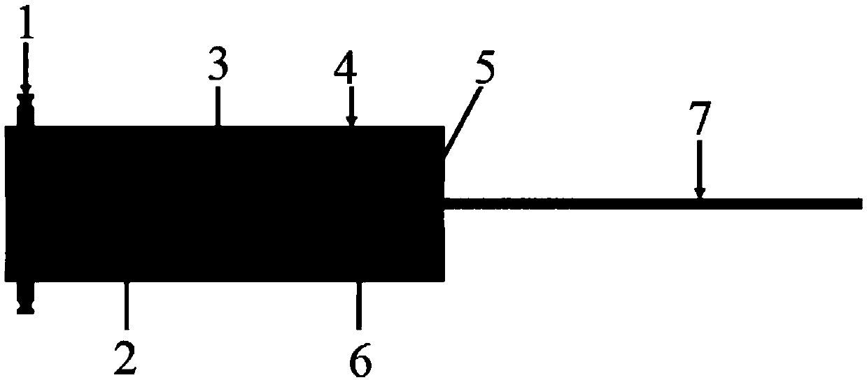
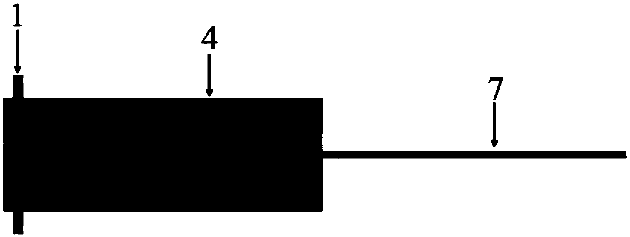
[0025] The repulsive force of the electromagnet is proportional to the voltage, that is, the higher the voltage, the higher the repulsive force, and vice versa. However, compared with the magnetic adsorption of the prior art, when the magnetic field 3 generates a certain amount of repulsive force, the magnet 2 immediately Propelled by the repulsive force, when reaching a certain distance, the magnet 2 stops moving and can only continue moving after further voltage is provided. Generate electromagnetic repulsion force with the permanent magnet 5 of the second module, thereby pushing away from each other. However, the second module in the first module is pushed by the electromagnetic repulsion force and gradually moves away from the first module. At this time, through this special structure, the traction wire harness 7 is converted into a pulling force, and this certain amount of pulling force can be maintained. , and change according to the level of the electromagnetic repulsio...


PUM


Abstract

The invention discloses a magnetic simulation muscle structure which is provided with a first module, and a second module arranged in the first module; and the first module and the second module can be moved relatively through electromagnetic repulsion force. The simulation muscle structure is a simulation muscle device using the electromagnetic repulsion force, and a traditional driving mode using a servo motor as a robot is changed completely. Compared with another driving mode using electromagnetic attraction, the magnetic simulation muscle structure has the effects that the controllable expansion degree is achieved on the expansion stroke of simulation muscle is achieved, while the electromagnetic attraction can only attract and release once, namely that only one-time extension and contraction can be achieved, and the expansion degree of the electromagnetic attraction can not be controlled. Thus, the magnetic simulation muscle structure is achieved by using the repulsion force of amagnetic field, namely that not only can any expansion degree of the simulation muscle be achieved, but also control over the size of the required force can be achieved. Therefore, the magnetic simulation muscle structure has the advantages of high acceleration, low mechanical wear, small size, light weight, low noise, energy saving, high response speed, controllable expansion degree and other excellent driving characteristics.

Description

technical field [0001] The invention relates to an electromagnetic force drive device, in particular to a muscle bionic drive device based on electromagnetic field repulsion force. Belonging to the fields of mechanical engineering, automation and robotics, it is used to imitate the muscle structure and movement form of mammalian skeletal muscle. Background technique [0002] With the advancement of science and technology, the application of electromagnetic force has promoted technologies such as mechanical engineering and automation. Especially in the fields of precision machinery and robotics research, the application of electromagnetic force is becoming more and more mature. The design of bionic muscle driving device based on the principle of electromagnetics has a good theoretical and practical basis. The electromagnetic force-driven bionic muscle driving device has a high response frequency. big advantage. [0003] Compared with the traditional non-linear motor drive, ...

Claims


Application Information

Patent Timeline
IPC IPC(8): B25J9/10
CPCB25J9/10B25J9/1075
Inventor 曾文彬
Owner 广东协禾医业有限公司
Learn More