Electric-driven speed changing device integrating heat dissipation, lubricating and electrically-controlled brake

A technology of speed change device and electric control brake, which is applied in the direction of electromechanical device, transmission device parts, brake parts, etc., can solve the problems of inability to realize integrated hoisting, occupy large volume, and have many connection interfaces, and achieve compact structure and workability. Safe and reliable, the effect of reducing failure points

Active Publication Date: 2019-04-26
JIANGLU MACHINERY & ELECTRONICS GROUP
6 Cites 1 Cited by

AI-Extracted Technical Summary

Problems solved by technology

[0003] However, the motors, transmission mechanisms, braking mechanisms, cooling systems, electric control systems, hydraulic systems, and lubrication systems in most existing electric transmission devices are all matched separately and arranged in a decentralized manner, without an integrated and integrated design Planning, the current integrated research is only biased toward...

Method used

[0026] Preferably, the oil tank 21 is provided with a strainer 18, and the oil inlet of the strainer 18 is arranged at the bottom center of the oil tank 21. ...

Abstract

The invention discloses an electric-driven speed changing device integrating heat dissipation, lubricating and electrical-controlled brake. The electric-driven speed changing device comprises a motor,a speed changing mechanism, a braking mechanism, a radiator, an electric control system, a hydraulic system and a lubricating system, wherein the braking mechanism is arranged at the tail end of themotor; a braking mechanism output end housing at the end of the braking mechanism and a motor tail end housing are integrally formed; a motor output end housing on the motor and a speed changing mechanism input end housing are integrally formed; the hydraulic system comprises pumps and a fuel tank, wherein the fuel tank is arranged at the bottom of the speed changing mechanism; the lubricating system comprises a radiator; the pumps comprise a large pump and a small pump; the large pump is used for providing operating oil pressure for the speed changing mechanism and the braking mechanism; andthe small pump is used for supplying oil to perform heat dissipation and lubrication of parts. The invention aims to provide the electric-driven speed changing device integrating heat dissipation, lubricating and electrically-controlled brake, and the device has the advantages of being high in integrity, compact in structure, small in occupied space, low in manufacturing cost, convenient to disassemble, assemble and maintain, good in control characteristics, safe and reliable to work and the like.

Application Domain

Gear lubrication/coolingMechanical energy handling +2

Technology Topic

Electric driveElectrical control +8

Image

  • Electric-driven speed changing device integrating heat dissipation, lubricating and electrically-controlled brake
  • Electric-driven speed changing device integrating heat dissipation, lubricating and electrically-controlled brake

Examples

  • Experimental program(1)

Example Embodiment

[0022] In order to enable those skilled in the art to better understand the technical solutions of the present invention, the present invention will be described in detail below with reference to the accompanying drawings. The description in this section is only exemplary and explanatory and should not have any limitation on the scope of protection of the present invention. .
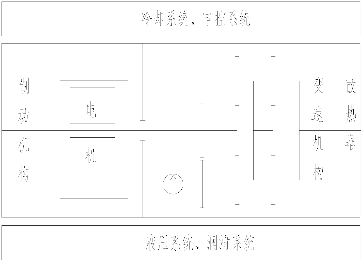
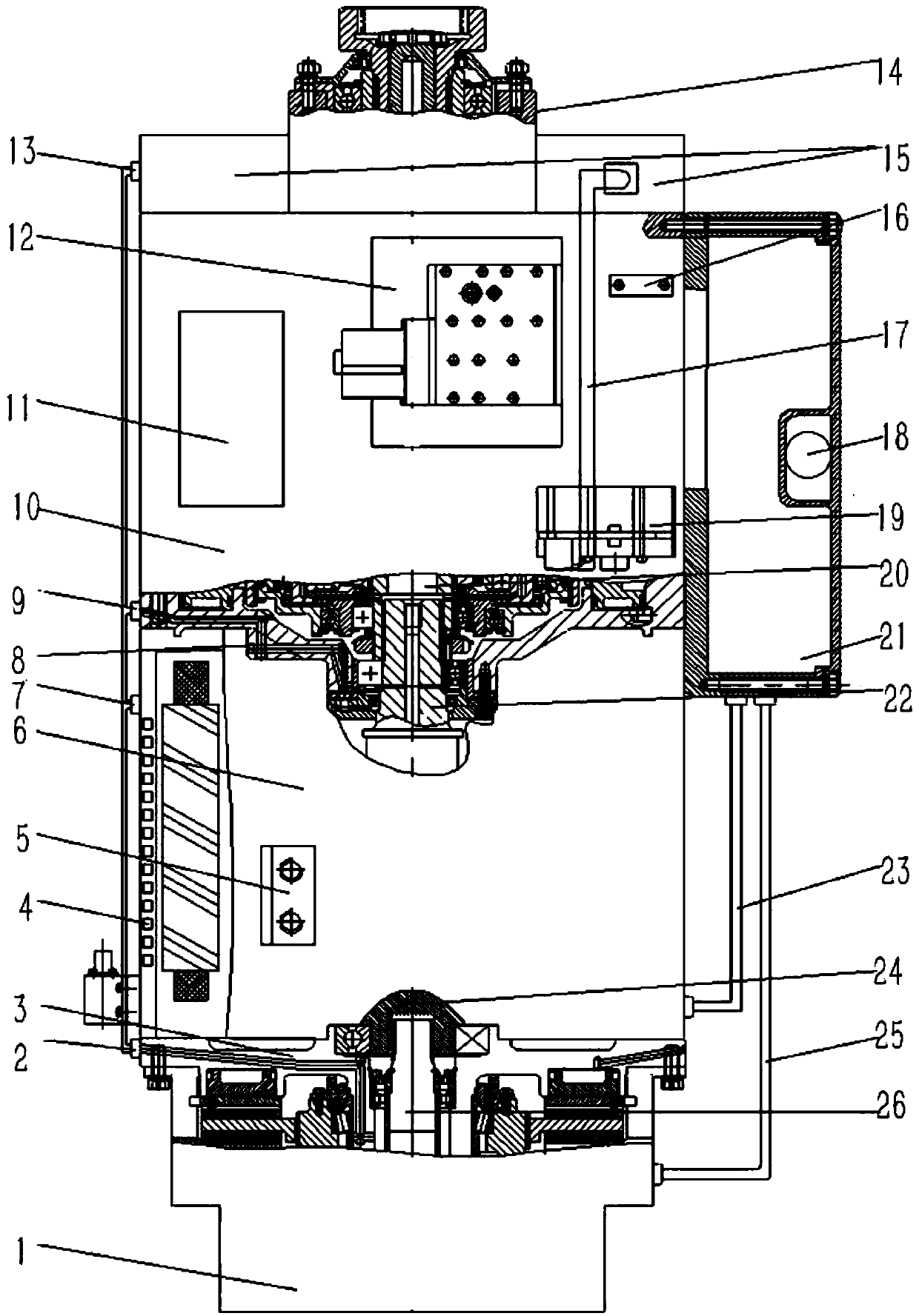
[0023] Such as Figure 1-2 As shown, the specific structure of the present invention is: an electric drive transmission device integrating heat dissipation, lubrication and electric control, including a motor 6, a transmission mechanism 10, a braking mechanism 1, a radiator 15, an electronic control system 11, and a hydraulic System and lubrication system, the braking mechanism 1 is arranged at the end of the motor 6, the braking mechanism transmission shaft 26 on the braking mechanism 1 is drivingly connected to the motor tail shaft 24, and the braking mechanism at the end of the braking mechanism 1 The output end housing 3 of the mechanism and the end housing of the motor 6 are integrally formed; the integration of the braking mechanism 1 and the motor 6 is realized, which greatly reduces the overall space occupied. The motor output shaft 22 on the motor 6 is in transmission connection with the transmission mechanism input shaft 20 on the transmission mechanism 10, and the motor output end housing 8 on the motor 6 is integrally formed with the input end housing of the transmission mechanism 10; The overall space is occupied, and the integration of the motor 6 and the speed change mechanism 10 is realized. The electronic control system 11 is used to control the start and stop of the electric motor 6, the transmission mechanism 10, the brake mechanism 1, the radiator 15, the hydraulic system and the lubrication system; the hydraulic system includes a pump 19 and an oil tank 21, and the oil tank 21 is provided with At the bottom of the speed change mechanism 10; the lubrication system includes a radiator 15; the entire hydraulic system is integrated in the device, which greatly reduces the overall space occupied. The pump 19 includes a large pump and a small pump. The output port of the large pump is connected to the working oil inlet of the transmission mechanism 10 and the working oil inlet of the brake mechanism 1 respectively. The working return of the transmission mechanism 10 is The oil port communicates with the oil tank 21, and the working oil return port of the brake mechanism 1 communicates with the oil tank 21 through the brake mechanism oil return pipe 25; the large pump provides working oil pressure for the transmission mechanism 10 and the braking mechanism 1, and the transmission mechanism 10 works The oil is directly returned to the oil tank 21, and the working oil of the brake mechanism 1 is returned to the oil tank 21 through the brake mechanism oil return pipe 25, so that the working oil forms a self-circulation. The cooling system of the motor 6, the speed change mechanism 10 and the brake mechanism 1 are connected in parallel and share a radiator 15; the output port of the small pump is connected to the oil inlet of the radiator 15 (ie the radiator oil inlet pipe 17) The oil outlet of the radiator 15 (ie, the radiator oil outlet pipe 13) is connected to the inlet pipe of the motor cooling structure 4 through the motor heat dissipation oil inlet pipe 7, and the outlet of the motor cooling structure 4 is connected to the motor cooling oil return pipe 23 through the motor cooling oil inlet pipe 7 The oil tank 21 is connected to the pipeline; the small pump sucks oil from the oil tank into the radiator 15 to cool the oil in the oil tank 21, and the cooled oil enters the motor cooling structure 4 to cool the motor 6, and the oil from the motor 6 is cooled The cooling oil return pipe 23 returns to the oil tank 21 to form a self-circulation of motor cooling oil. The oil outlet of the radiator 15 (ie, the oil outlet pipe 13 of the radiator) enters the brake mechanism 1 through the lubrication oil inlet pipe 2 of the brake mechanism, and the brake mechanism oil return pipe 25 on the brake mechanism 1 is connected to the oil tank 21 The oil outlet of the radiator 15 enters the transmission mechanism 10 through the transmission mechanism lubrication oil inlet pipe 9, and the transmission mechanism 10 is in communication with the oil tank 21; at the same time, the oil cooled from the radiator 15 is lubricated by the brake mechanism The oil inlet pipe 2 enters the brake mechanism 1 for lubrication. After lubrication, the oil returns from the brake mechanism oil return pipe 25 to the oil tank 21 to form a self-circulation of the lubricating oil of the brake mechanism 1. The oil inlet pipe 9 enters the transmission mechanism through the transmission mechanism lubrication It is lubricated and directly returned to the tank to form a self-circulation. This direct use of the system working oil as the cooling medium of the motor 6 integrates the cooling of the motor 6, the braking mechanism 1, and the transmission mechanism 10, which greatly simplifies the cooling structure, reduces failure points, and improves the reliability of the overall structure. Through the above reasonable adoption of a common body, a common cooling structure, a common hydraulic control system, etc., a highly integrated motor, transmission mechanism, braking mechanism, cooling system, electronic control system, hydraulic system, and lubrication system is realized. Electric drive.
[0024] Preferably, the speed change mechanism 10 is a planetary gear reducer.
[0025] Preferably, a first support point 5 is provided on the side of the motor 6, and a second support point 14 is provided on the output end of the speed change mechanism 10.
[0026] Preferably, a coarse filter 18 is provided in the oil tank 21, and the oil inlet of the coarse filter 18 is arranged at the center of the bottom of the oil tank 21. Ensure that the transmission effectively returns oil when the vehicle is tilted longitudinally and laterally, reducing the need for fuel tank depth.
[0027] Preferably, the pump 19 is a double gear pump.
[0028] Preferably, the motor cooling structure 4 includes a cooling water tank and a cooling water pipe, the cooling water tank is opened on the outer side wall of the motor stator, and the cooling water pipe is laid in the cooling water tank.
[0029] Preferably, the hydraulic system further includes a control valve group 12, and a large pump on the pump 19 provides working oil pressure for the control valve group 12.
[0030] Preferably, an oil mark 16 is further provided above the oil tank 21.
[0031] It should be noted that in this article, the terms "include", "include" or any other variants thereof are intended to cover non-exclusive inclusion, so that a process, method, article or device including a series of elements not only includes those elements, It also includes other elements not explicitly listed, or elements inherent to the process, method, article, or equipment.
[0032] Specific examples are used in this article to illustrate the principle and implementation of the present invention. The description of the above examples is only used to help understand the method and core idea of ​​the present invention. The above are only the preferred embodiments of the present invention. It should be pointed out that due to the limited expression of words, there are objectively infinite specific structures. For those of ordinary skill in the art, the principle of the present invention is not deviated from the premise Next, several improvements, modifications or changes can also be made, or the above technical features can be combined in an appropriate manner; these improvements, changes or combinations, or the concept and technical solution of the invention can be directly applied to other occasions without improvement , Should be regarded as the protection scope of the present invention.

PUM

no PUM

Description & Claims & Application Information

We can also present the details of the Description, Claims and Application information to help users get a comprehensive understanding of the technical details of the patent, such as background art, summary of invention, brief description of drawings, description of embodiments, and other original content. On the other hand, users can also determine the specific scope of protection of the technology through the list of claims; as well as understand the changes in the life cycle of the technology with the presentation of the patent timeline. Login to view more.

Similar technology patents

Intelligent express item management system with error detection function and control method of intelligent express item management system

ActiveCN106391484AHighly integratedStrengthen comprehensive management
Owner:紫光智云(江苏)物联网科技有限公司

Intelligent electrical valve locator main board hardware circuit

InactiveCN103343831AHighly integratedgood suppression effect
Owner:TIANJIN JINGTONG CONTROL INSTR TECH

Visual image processing system and design method thereof

InactiveCN107071324AHighly integratedFast on-chip communication
Owner:SHANGHAI ELECTRICGROUP CORP

Classification and recommendation of technical efficacy words

  • Highly integrated
  • compact structure

Vehicle-mounted information center control unit

InactiveCN102594929AHighly integratedHigh degree of fault identification
Owner:TIANJIN FAW XIALI AUTOMOBILE +1
Why Eureka
Try Eureka