Atmospheric pressure hot blast stove

A technology of hot blast stove and normal pressure, which is applied in air heaters, fluid heaters, lighting and heating equipment, etc. It can solve the problems of no flue gas heat energy, low thermal conductivity, and recovery, so as to reduce production costs and improve heat transfer Efficiency, the effect of lowering the discharge temperature

Active Publication Date: 2019-04-26
黎汉东
View PDF6 Cites 0 Cited by
  • Summary
  • Abstract
  • Description
  • Claims
  • Application Information

AI Technical Summary

Problems solved by technology

Since the air duct is arranged in the furnace, the temperature in the furnace is relatively high, and the melting point of the aluminum pipe is 635°C. The aluminum pipe cannot be directly arranged in the furnace as an air duct. The air duct can only use steel, iron, copper, etc. with high melting points. The material pipe is used as the air pipe; but the inner wall of the steel pipe and iron pipe is easy to rust, and the hot air exported will be unclean; when hot air with a high cleaning rate is required, the air pipe can only choose stainless steel pipe or copper pipe; stainless steel pipe and copper pipe are used Tubes as air ducts have their own advantages and disadvantages: stainless steel tubes are cheap, but their thermal conductivity is low, only about 17, and the heat conversion rate is low; copper tubes are expensive, and their thermal conductivity is as high as 380
When there is no requirement for the cleanliness rate of the hot air, steel, iron, copper and other materials with high melting points can be used as the air duct, but the heat energy of the flue gas is not recovered, and the heat is not fully utilized.

Method used


Image

  • Atmospheric pressure hot blast stove
  • Atmospheric pressure hot blast stove
  • Atmospheric pressure hot blast stove

Examples


Embodiment 1

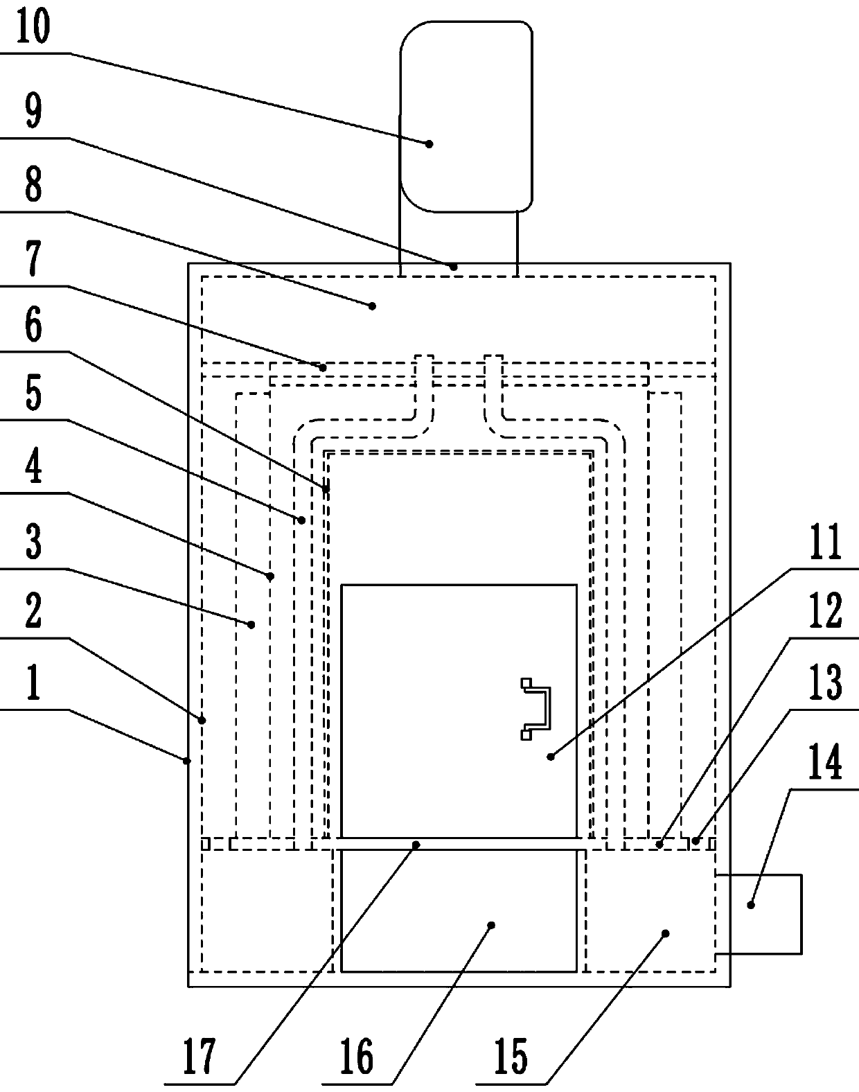
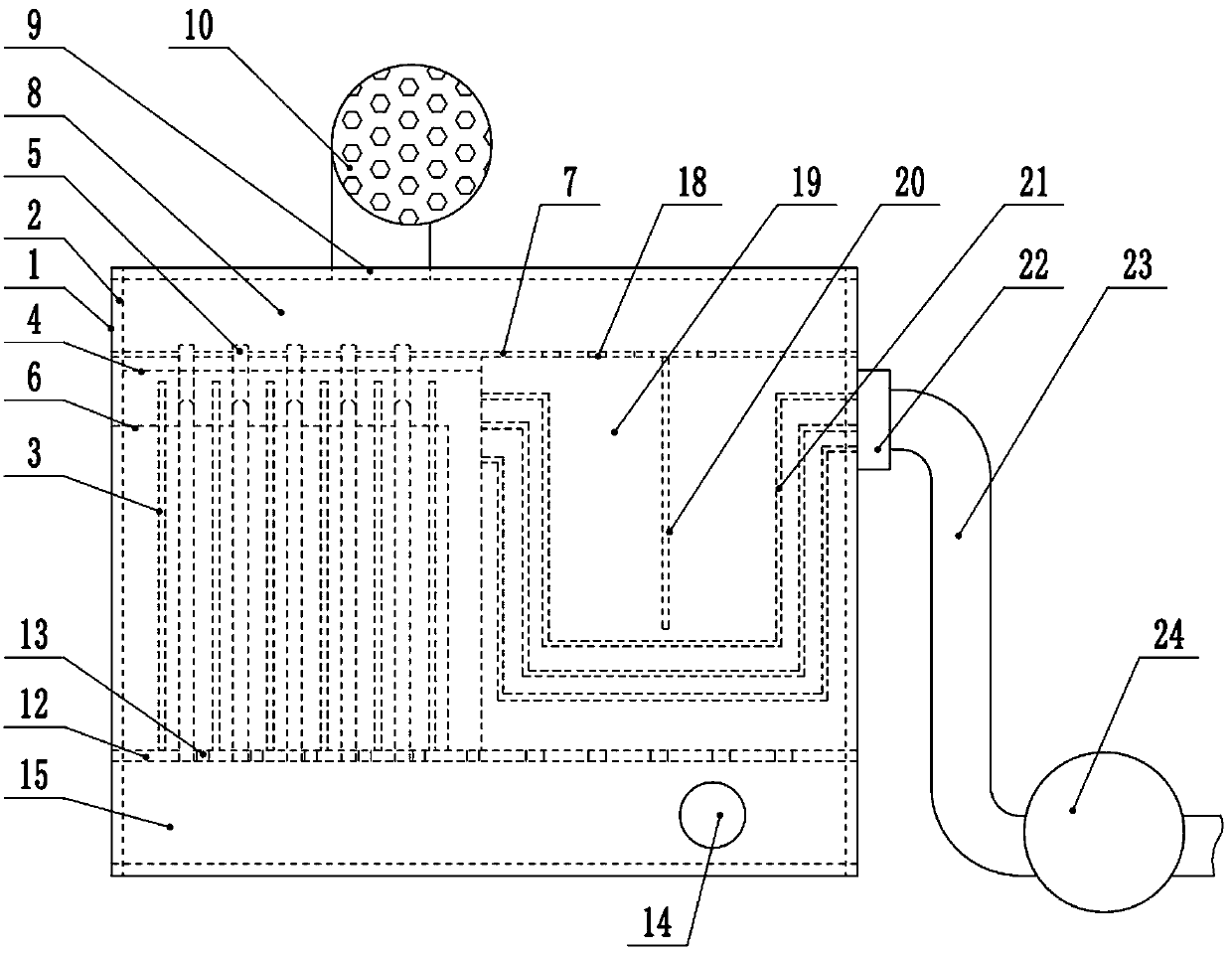
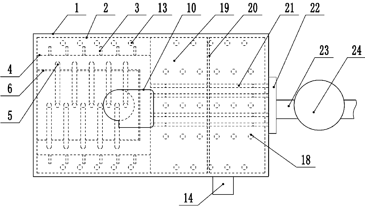
[0029] A kind of normal pressure hot blast stove, comprises furnace shell 1 and furnace wall 4, described furnace shell 1 inner wall is provided with insulation layer 2, the front of furnace shell 1 is provided with furnace door 11; Furnace wall 4 is arranged in furnace shell 1, The furnace wall 4 on the side away from the furnace door 11 is provided with a smoke exhaust port, the bottom of the furnace wall 4 is provided with a grate 17, the lower part of the grate 17 is provided with an ash collection chamber 16, and the lower part of the furnace shell 1 is provided with a hot air chamber interlayer 12, The hot air bin interlayer 12 separates the two sides and the rear of the ash collecting chamber 16 into interconnected hot air bins 15; the hot air bin 15 is provided with a hot air outlet 14, and the hot air discharged from the hot air outlet 14 is transported to the place where hot air is needed through the hot air delivery pipe; The top of the furnace wall 4 is provided wit...

Embodiment 2

[0031] A kind of normal pressure hot blast stove, comprises furnace shell 1 and furnace wall 4, described furnace shell 1 inner wall is provided with insulation layer 2, the front of furnace shell 1 is provided with furnace door 11; Furnace wall 4 is arranged in furnace shell 1, The furnace wall 4 on the side away from the furnace door 11 is provided with a smoke exhaust port, the bottom of the furnace wall 4 is provided with a grate 17, the lower part of the grate 17 is provided with an ash collection chamber 16, and the lower part of the furnace shell 1 is provided with a hot air chamber interlayer 12, The hot air bin interlayer 12 separates the two sides and the rear of the ash collecting chamber 16 into interconnected hot air bins 15; the hot air bin 15 is provided with a hot air outlet 14, and the hot air discharged from the hot air outlet 14 is transported to the place where hot air is needed through the hot air delivery pipe; The top of the furnace wall 4 is provided wit...

Embodiment 3

[0034] A kind of normal pressure hot blast stove, comprises furnace shell 1 and furnace wall 4, described furnace shell 1 inner wall is provided with insulation layer 2, the front of furnace shell 1 is provided with furnace door 11; Furnace wall 4 is arranged in furnace shell 1, The furnace wall 4 on the side away from the furnace door 11 is provided with a smoke exhaust port, the bottom of the furnace wall 4 is provided with a grate 17, the lower part of the grate 17 is provided with an ash collection chamber 16, and the lower part of the furnace shell 1 is provided with a hot air chamber interlayer 12, The hot air bin interlayer 12 separates the two sides and the rear of the ash collecting chamber 16 into interconnected hot air bins 15; the hot air bin 15 is provided with a hot air outlet 14, and the hot air discharged from the hot air outlet 14 is transported to the place where hot air is needed through the hot air delivery pipe; The top of the furnace wall 4 is provided wit...


PUM


Abstract

The invention discloses an atmospheric pressure hot blast stove comprising a stove casing and a furnace wall. The inner wall of the stove casing is provided with a thermal insulation layer, and the front side of the stove casing is provided with a stove door; the furnace wall is arranged in the stove casing, and the part, far away from a stove door side, of the furnace wall is provided with a smoke outlet; the bottom of the furnace wall is provided with a grate of which the lower part is provided with an ash collecting chamber, and the both sides and the rear part of the ash collecting chamberare provided with hot air compartments; each hot air compartment is provided with a hot air outlet; the top of the furnace wall is provided with an air inlet compartment; the air inlet compartment isprovided with an air inlet which is provided with a blower; the atmospheric pressure hot blast stove further comprises an equalizer, and the equalizer is in the shape of a hollow square column or a cylinder; one end face or one end face and bottom surface of the equalizer are not closed, and other faces of the equalizer are provided with a plurality of small holes; the interior of the equalizer is used as a combustion chamber; a plurality of air ducts made of aluminum are installed between the equalizer and the furnace wall; and the upper ends of the air ducts communicate with the air inlet compartments, and the lower ends of the air ducts communicate with the hot air compartments. The hot blast stove is simple in structure and low in cost, and the thermal energy conversion rate can reach90% and above.

Description

technical field [0001] The invention relates to the technical field of hot blast stove equipment, in particular to an atmospheric hot blast stove. technical background [0002] The hot blast stove is a thermal power machine, which was widely used in our country in the late 1970s. It has become a replacement product for electric heat sources and traditional steam power heat sources in many industries. There are many varieties and complete series of hot blast stoves, which are divided into two types: hand-fired and machine-fired according to the way of coal feeding, and divided into coal, oil, and gas stoves according to the type of fuel. [0003] At present, there are two types of hot blast stoves: direct-fired and indirect heat-exchanging. In direct-fired hot-blast stoves, due to the long-term operation of the tube wall at high temperature, high-temperature oxidation occurs so that its mechanical properties are destroyed, and cracks often occur on the tube wall and weld join...

Claims


Application Information

Patent Timeline
Patent Type & Authority Applications(China)
IPC IPC(8): F24H3/00F24H9/18F24H9/00F23J15/06
CPCF23J15/06F24H3/00F24H9/0052F24H9/1854
Inventor 黎汉东
Owner 黎汉东
Why Eureka
Try Eureka