Body fluid signal monitoring system based on remote data acquisition

A signal monitoring and remote data technology, applied in the extraction and delivery system, medical science, material inspection, etc., can solve the problems of poor sealing, leakage, fragile and drain valve, etc., to improve the quality and level, medical treatment. The effect of safe and reliable, convenient discharge situation

Inactive Publication Date: 2019-04-26
余晓飞
View PDF25 Cites 0 Cited by
  • Summary
  • Abstract
  • Description
  • Claims
  • Application Information

AI Technical Summary

Problems solved by technology

[0004] Not limited to the patient body fluid collection devices listed above generally have the following disadvantages: First, because the liquid discharge valve cannot be matched with a metering device such as a metering pump, it affects the medical staff's accurate grasp of the patient's body fluid volume, and ultimately affects the patient's medication. Therapeutic effect, because there is a causal relationship between the doctor's medication and the degree and volume of the patient's fluid discharge, although there are scale lines on the bag body, there are often large errors in observation with the scale line; The part of the drain valve tube bundle, so the drain valve is usually stretched out of the bag edge, so it is vulnerable to damage to the drain valve in links such as packaging, transportation and storage, and it also produces damage to surrounding objects during clinical use. The third is that the drainage pipeline and the liquid discharge valve are usually combined in the bag body production process, so not only the production is troublesome, but also there is a risk of leakage due to poor sealing fit; the fourth is that there is no medical staff A component that randomly samples a patient's bodily fluid for testing, making it cumbersome to take a small sample of bodily fluid

Method used


Image

  • Body fluid signal monitoring system based on remote data acquisition
  • Body fluid signal monitoring system based on remote data acquisition
  • Body fluid signal monitoring system based on remote data acquisition

Examples


Embodiment Construction

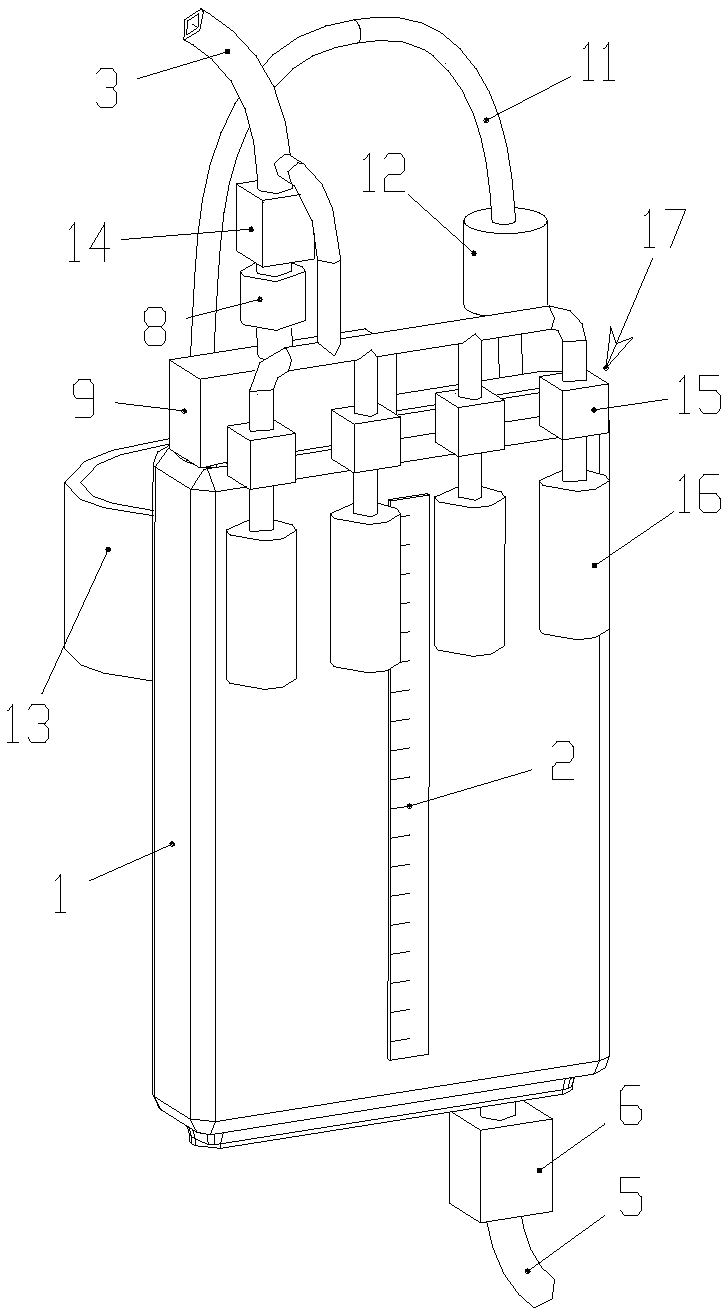
[0030] The present invention will be further described in detail below in conjunction with the accompanying drawings, but does not constitute any limitation to the present invention. Similar component numbers in the accompanying drawings represent similar components. All the following concepts involving orientation or directionality such as up, down, left, and right are based on figure 1 The position status shown is an example. As mentioned above, the present invention provides a body fluid signal monitoring system based on remote data acquisition, which has a simple structure and is easy to operate.

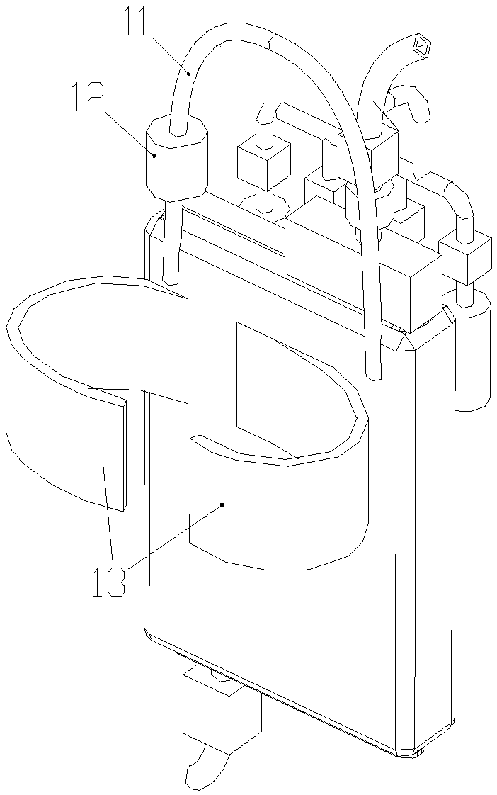
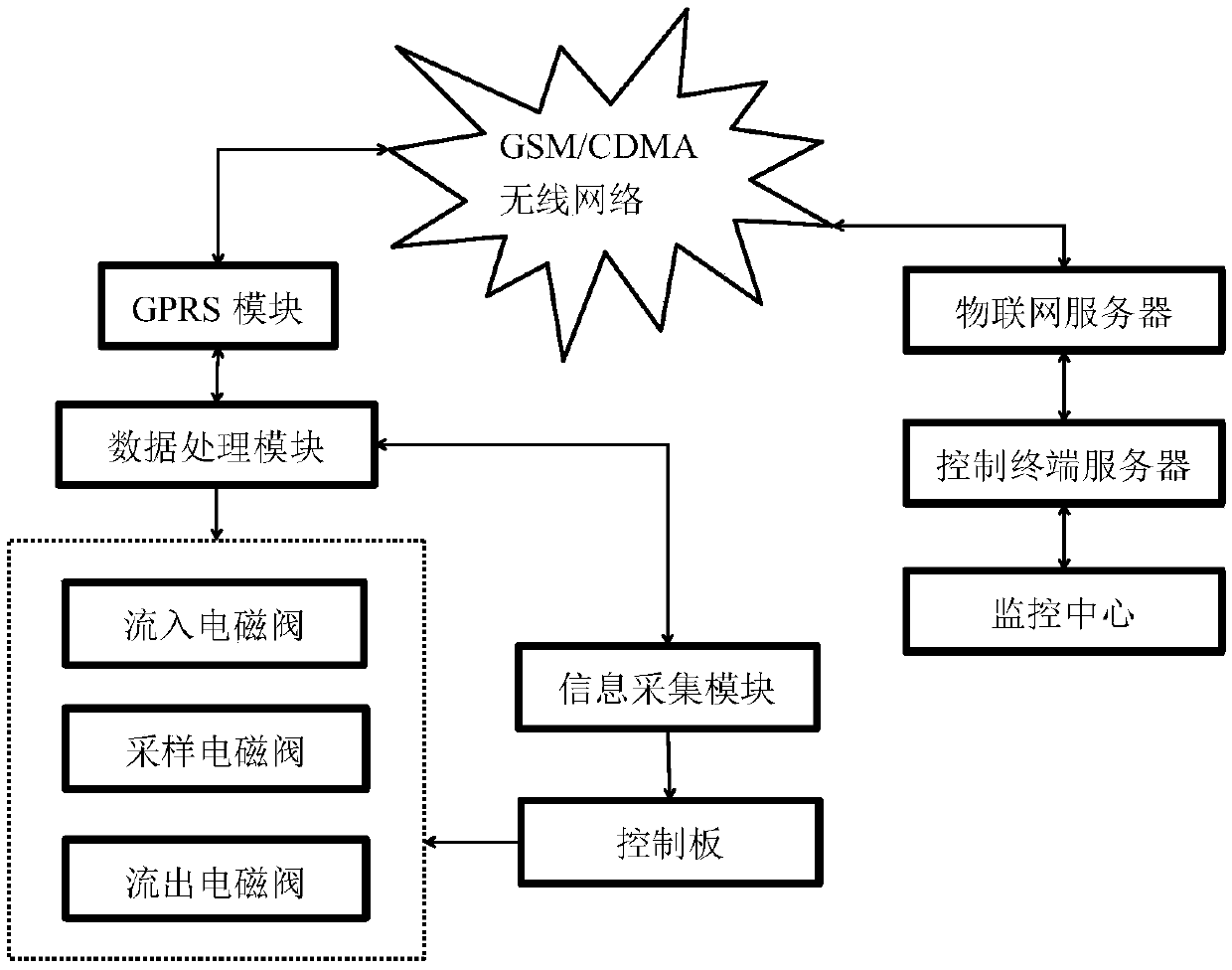
[0031] figure 1 , 2 It is a schematic structural diagram of the body fluid signal monitoring system based on remote data acquisition of the present invention; image 3 , 4 It is a structural schematic diagram of the control method of the body fluid signal monitoring system based on remote data collection in the present invention.

[0032] A body fluid signal monitoring syst...


PUM


Abstract

The invention relates to a liquid collecting container and a remote control method, in particular to a device for collecting and storing body fluid discharged by a human body. The invention disclosesa body fluid signal monitoring system based on remote data acquisition, which comprises a cavity, an inflow pipe, a discharge pipe, an outflow electromagnetic valve, a one-way valve and a flow valve,wherein the upper part of the cavity is provided with an inflow mechanism, and the lower part of the cavity is provided with an outflow mechanism; the one-way valve is positioned at the upper part ofthe flow valve; a binding band is arranged at the middle position of the cavity; the upper part of the cavity is provided with a hanging ring, the hanging ring is provided with an electronic scale, and the middle position of the cavity is provided with the binding band. The body fluid signal monitoring system based on remote data acquisition is used for storing body fluid, sampling the body fluid,monitoring information such as the flow rate of the body fluid and the like, and assisting medical personnel to formulate a more scientific treatment scheme through the remote control method.

Description

technical field [0001] The present invention is a divisional application, and the application number of the parent application is: 2016100495588. The invention relates to a liquid collection container and a remote control method, more specifically, to a device for collecting and storing body fluid discharged from a human body. Background technique [0002] Patient's bodily fluid such as urine and thoracoperitoneal drainage fluid, etc., take the urine collecting device material of collecting patient's urine as example, can be seen in a large number in the open Chinese patent literature, slightly enumerate as CN1282451C (medical semi-automatic urine liquid metering storage), ZL02123886.3 (medical semi-automatic urine metering storage), ZL91225245.6 (disposable metering plastic urine bag), ZL94242826.9 (disposable precision metering double-chamber urine drainage device), ZL97211613.3 (a kind of measuring urine accumulation bottle), ZL99209573.5 (urination measuring bottle), ZL...

Claims


Application Information

Patent Timeline
Patent Type & Authority Applications(China)
IPC IPC(8): G01N33/48G01N1/20A61B10/00A61M1/00
CPCA61B10/0045A61M1/0023G01N1/20G01N33/48
Inventor 不公告发明人
Owner 余晓飞
Why Eureka
Try Eureka