Chaotic modulation speckle-free laser projector

A laser projector and chaotic modulation technology, applied in optics, instruments, optical components, etc., can solve the problems of low speckle suppression efficiency and complex system, and achieve the effect of good projection effect, high frequency and simple device

Active Publication Date: 2019-04-26
TAIYUAN UNIV OF TECH
View PDF6 Cites 2 Cited by
  • Summary
  • Abstract
  • Description
  • Claims
  • Application Information

AI Technical Summary

Problems solved by technology

[0003] In order to solve the problem that the existing laser projection speckle suppression system is complicated and the s...

Method used


Image

  • Chaotic modulation speckle-free laser projector
  • Chaotic modulation speckle-free laser projector

Examples


Embodiment 1

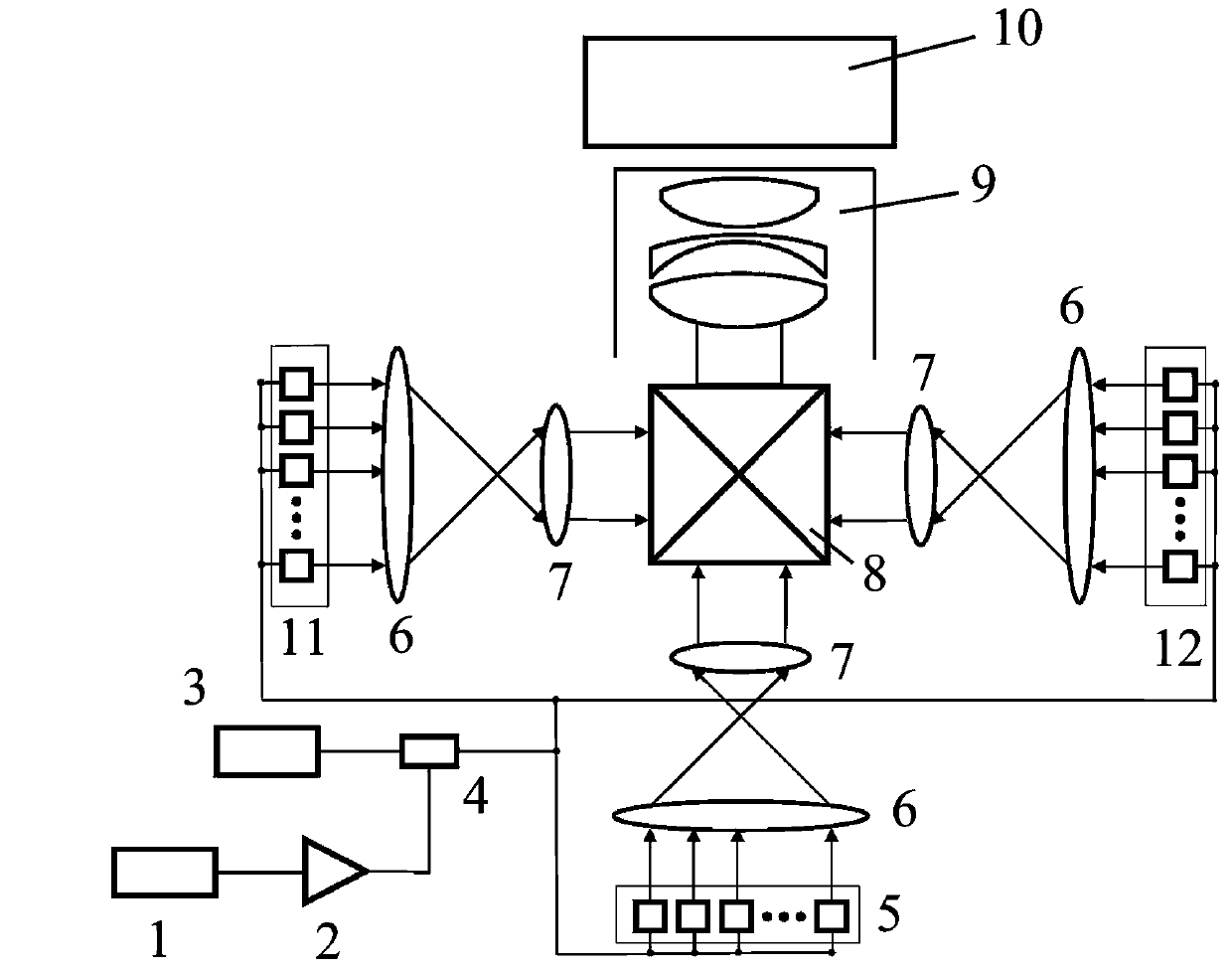
[0018] In this embodiment, the preferred scheme is adopted: as figure 1 As shown, several groups of laser arrays include a group of green laser arrays 5, a group of blue laser arrays 11, and a group of red laser arrays 12; the chaotic electrical signal generating device 1 is a chaotic circuit. In this embodiment, a Colpitts circuit is used, and a converging lens 6 is a high-curvature uniform converging lens, and the color-combining component 8 is a color-combining prism.

[0019] The specific operation of this embodiment is: the chaotic electrical signal generating device 1, that is, the Colpitts circuit, generates the chaotic electrical signal, inputs it into the broadband amplifier 2, amplifies the chaotic electrical signal, and inputs it into the biaser 4, and the driving voltage of the laser drive circuit 3 is also inputted into the biaser 4. After the two are mixed, the green laser array 5, the blue laser array 11 and the red laser array 12 are driven to emit light throug...

Embodiment 2

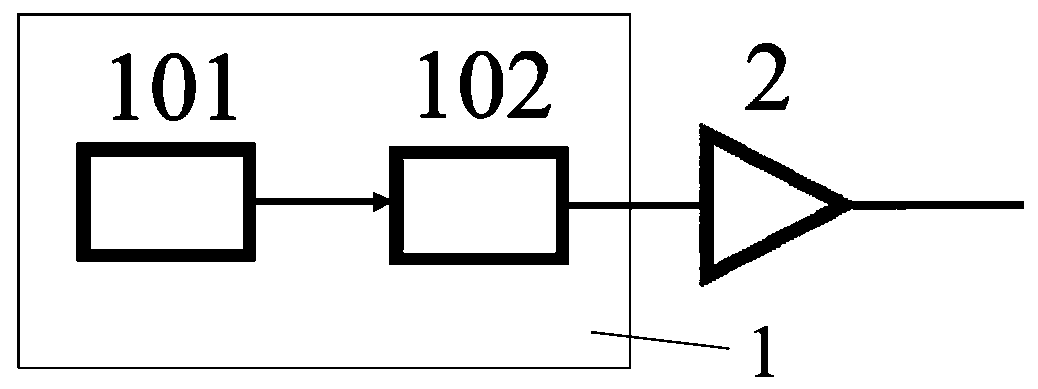
[0021] In this embodiment, the preferred scheme is adopted: as figure 2As shown, several groups of laser arrays include a group of green laser arrays 5, a group of blue laser arrays 11 and a group of red laser arrays 12; the chaotic electrical signal generating device 1 is a broadband chaotic light source 101 and a high-speed photodetector 102, the The output end of the broadband chaotic light source 101 is connected with the input end of the high-speed photodetector 102, and the output end of the high-speed photodetector 102 is connected with the input end of the broadband amplifier 2, and the converging lens 6 is a high-curvature uniform converging lens, a color combining component 8 is a color combining prism.

[0022] The specific operation of this embodiment is as follows: the chaotic electrical signal generator 1, that is, the broadband chaotic light source 101, sends out a light source signal, inputs it into the high-speed photodetector 102, and after generating the br...


PUM


Abstract

The invention discloses a chaotic modulation speckle-free laser projector. The laser projector comprises a plurality of sets of laser device arrays, a laser device array driving device, a laser outputpart and a projection unit, wherein each laser device array is composed of a plurality of same-color laser devices; a respective convergent lens and a collimating lens are arranged behind each set oflaser device array along the light path, and the laser output part and the projection unit are arranged behind all the collimating lenses; the laser device array driving device comprises a chaotic electric signal generation device and a laser device driving circuit, the output end of the chaotic electric signal generation device is connected with the input end of a broadband amplifier, the broadband amplifier is output to a bias device, and the laser device driving circuit is output to the bias device; the bias device drives each laser device of the multiple sets of laser device arrays to emit light through a line with the delay larger than 0.3 ns or larger than 6 cm. The full-power output of the laser devices is guaranteed, speckles of the laser devices are inhibited, and the projectioneffect of the projector is better.

Description

technical field [0001] The invention relates to the field of laser light sources, in particular to a chaotic modulation speckle-free laser projector. Background technique [0002] With its high power, long life, and high degree of color reproduction, the three-color laser has attracted more and more attention, and has become the preferred light source for the next generation of projection display. At present, laser projectors use red, green and blue laser semiconductor (LD) arrays, which enter the projection unit through optical fibers or coupling lens systems to form a laser projection system. Due to its good coherence, the semiconductor laser will have strong speckle phenomenon on the projection screen, so it cannot be directly used as a projection light source. The current measures are to use elements such as phase plates or scattering plates to disturb its polarization state and phase, and reduce its coherence. These measures can only reduce the granularity and thicknes...

Claims


Application Information

Patent Timeline
IPC IPC(8): G02B27/48G03B21/20
CPCG02B27/48G03B21/2013G03B21/208
Inventor 赵彤贺培鑫韩红贾志伟韩国华郭园园
Owner TAIYUAN UNIV OF TECH
Why Eureka
Try Eureka